S1 S2
| S2 |
ON | ON |
1 2 3 4 5 6 7 8 | 1 2 3 4 5 6 7 8 |
S1 |
|
S1
Switch toggleON ![]()
|
|
|
|
|
| 7 | 8 |
|
|
|
|
| 6 |
| |
|
|
|
| 5 |
|
| |
|
|
| 4 |
|
|
| |
|
| 3 |
|
|
|
| |
| 2 |
|
|
|
|
| |
1 |
|
|
|
|
|
| |
|
|
|
|
|
|
|
Push toggle uONp
for ON position |
Push toggle |
down for 1 2 3 4 5 6 7 8 |
OFF position |
S1 |
ON
1 2
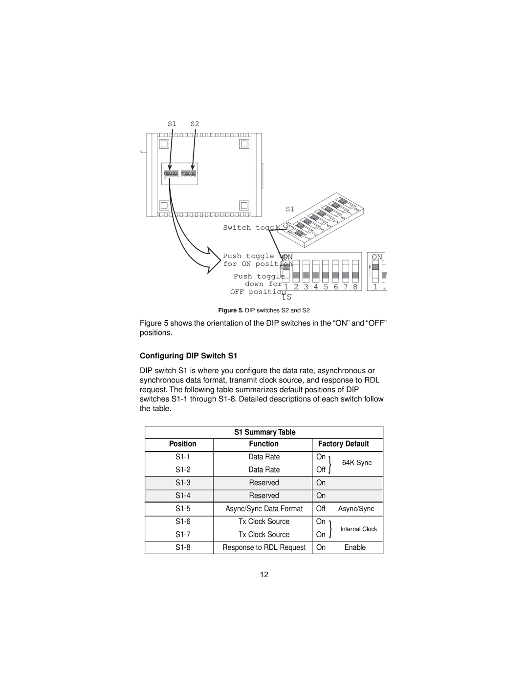
Figure 5. DIP switches S2 and S2
Figure 5 shows the orientation of the DIP switches in the “ON” and “OFF” positions.
Configuring DIP Switch S1
DIP switch S1 is where you configure the data rate, asynchronous or synchronous data format, transmit clock source, and response to RDL request. The following table summarizes default positions of DIP switches
S1 Summary Table
| Position | Function | Factory Default | ||
|
|
|
|
|
|
| Data Rate | On | } | 64K Sync | |
| Data Rate | Off | |||
|
|
|
|
|
|
| Reserved | On |
|
| |
|
|
|
|
|
|
| Reserved | On |
|
| |
| Async/Sync Data Format | Off |
| Async/Sync | |
|
|
|
|
|
|
| Tx Clock Source | On | } | Internal Clock | |
| Tx Clock Source | On | |||
|
|
|
|
|
|
| Response to RDL Request | On |
| Enable | |
|
|
|
|
|
|
12