5.0 INSTALLATION
When the Model 1082 has been properly configured, it may be con- nected to the DSL twisted pair interface, the
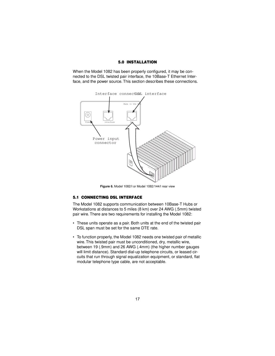
Interface connectorDSL interface
ON
PowerOFF O | Interface |
Made in the USA
DSL |
Power input connector
M | d | l | . | |
Power | G | . | ||
|
| 1194E |
| 703/G |
|
|
| Single | |
DSL
511EMade | in |
|
|
| the |
| |
|
| USA | |
- |
|
| |
|
|
| |
Quad |
|
|
|
G. |
|
|
|
703/G |
|
|
|
.704 |
|
| |
| Interface | ||
Figure 6. Model 1082/I or Model 1082/144/I rear view
5.1 CONNECTING DSL INTERFACE
The Model 1082 supports communication between
•These units operate as a pair. Both units at the end of the twisted pair DSL span must be set for the same DTE rate.
•To function properly, the Model 1082 needs one twisted pair of metallic wire. This twisted pair must be unconditioned, dry, metallic wire, between 19 (.9mm) and 26 AWG (.4mm) (the higher number gauges will limit distance). Standard
17