|
|
|
|
| Table 2: LED configurations |
|
|
|
|
| |||
|
|
|
|
|
|
|
|
|
|
|
|
|
|
|
|
|
| LOCAL |
|
|
|
|
| REMOTE |
|
|
|
|
|
|
|
|
|
|
|
|
|
|
|
|
|
|
| DSL | Status | NS | ER | TM | DSL | Status | NS | ER | TM | ||
|
|
|
|
|
|
|
|
|
|
|
|
|
|
Power ON | G* |
| off | F | on | off | off | G* | off | F | O | off | off |
|
|
|
|
|
|
|
|
|
|
| N |
|
|
|
|
|
|
|
|
|
|
|
|
|
|
|
|
DSL Link | G* |
| G | F | off | off | off | G* | off | F | off | off | off |
|
|
|
|
|
|
|
|
|
|
|
|
|
|
Link Brk | G* |
| off | F | off | off | off | G* | off | F | off | off | off |
|
|
|
|
|
|
|
|
|
|
|
|
|
|
Brk+ 10s | G* |
| off | F | ON | off | off | G* | off | F | O | off | off |
|
|
|
|
|
|
|
|
|
|
| N |
|
|
|
|
|
|
|
|
|
|
|
|
|
|
|
|
RDL | G* |
| G | F | off | off | ON | G* | off | F | off | off | ON |
|
|
|
|
|
|
|
|
|
|
|
|
|
|
RDL+511 | G* |
| off | F | off | off | ON | G* | off | F | off | off | ON |
|
|
|
|
|
|
|
|
|
|
|
|
|
|
|
| With DTE Connected |
|
|
|
| With DTE Connected |
|
| ||||
|
|
|
|
|
|
|
|
|
|
|
|
|
|
Mark | G* |
| G | F | off | off | off | G* | G | F | off | off | off |
|
|
|
|
|
|
|
|
|
|
|
|
|
|
Space | G* |
| G | F | off | off | off | G* | G | F | off | off | off |
|
|
|
|
|
|
|
|
|
|
|
|
|
|
Data | G* |
| G | F | off | off | off | G* | G | F | off | off | off |
|
|
|
|
|
|
|
|
|
|
|
|
|
|
G=GREEN |
|
|
|
|
|
|
|
|
|
|
|
|
|
O=ORANGE ON= ON off= OFF
Brk+10s = 10 Seconds following Link Break G*=Green if a valid
Link Brk = DSL Link Broken
6.3 TEST MODES
The Model 1082/I and Model 1082/144/I has a
Remote Digital Loopback (RDL)/V.52 (BER)
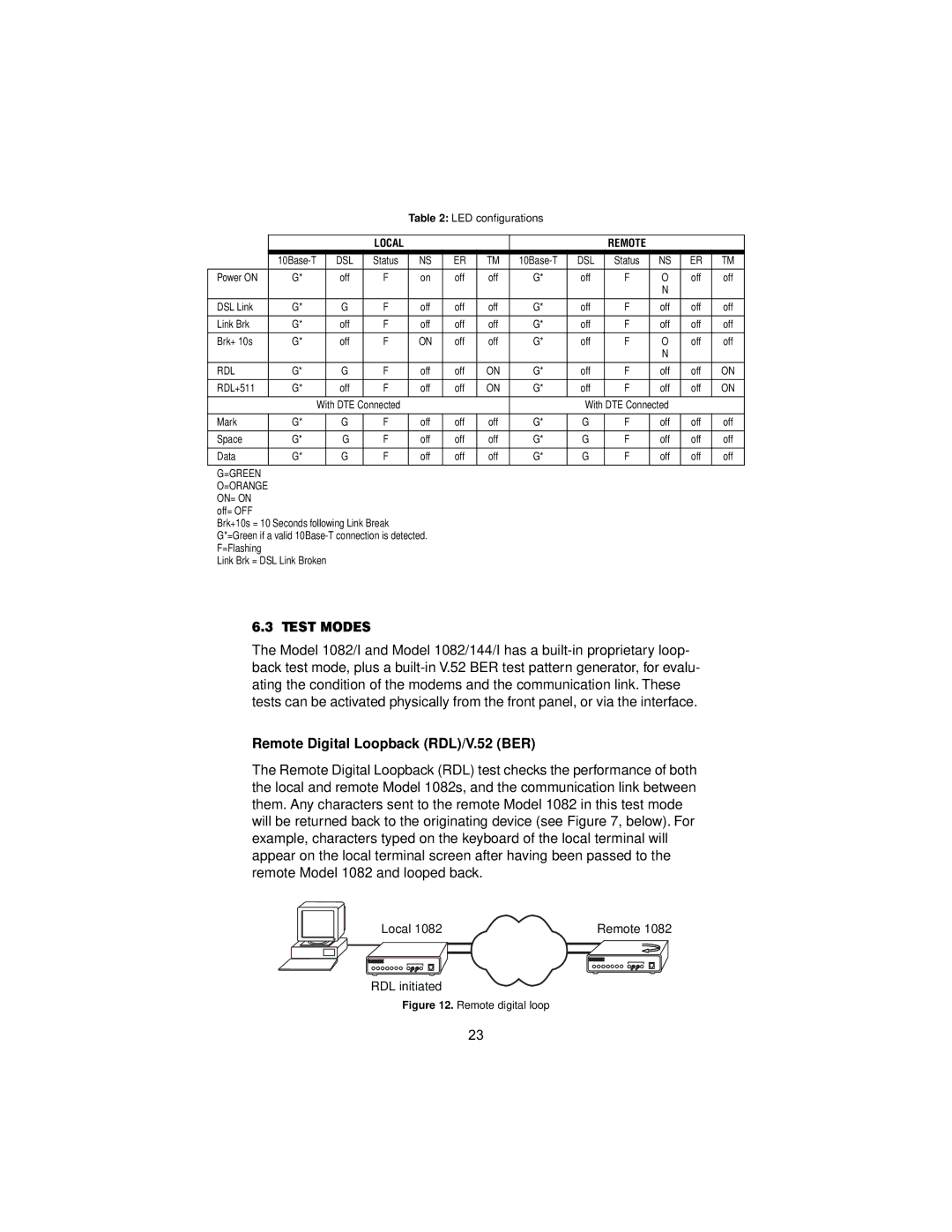
The Remote Digital Loopback (RDL) test checks the performance of both the local and remote Model 1082s, and the communication link between them. Any characters sent to the remote Model 1082 in this test mode will be returned back to the originating device (see Figure 7, below). For example, characters typed on the keyboard of the local terminal will appear on the local terminal screen after having been passed to the remote Model 1082 and looped back.
Local 1082 | Remote 1082 |
RDL initiated
Figure 12. Remote digital loop
23
