6.0 OPERATION
When the Model 1082/I and Model 1082/144/I have been properly config- ured and installed, it should operate transparently. This sections describes
6.1 POWER-UP
Before applying power to the Model 1082/I or Model 1082/144/I, please read section 5.4, “Power Connection” on page 19 and ensure that the unit is connected to the appropriate power source.
6.2 LED STATUS MONITORS
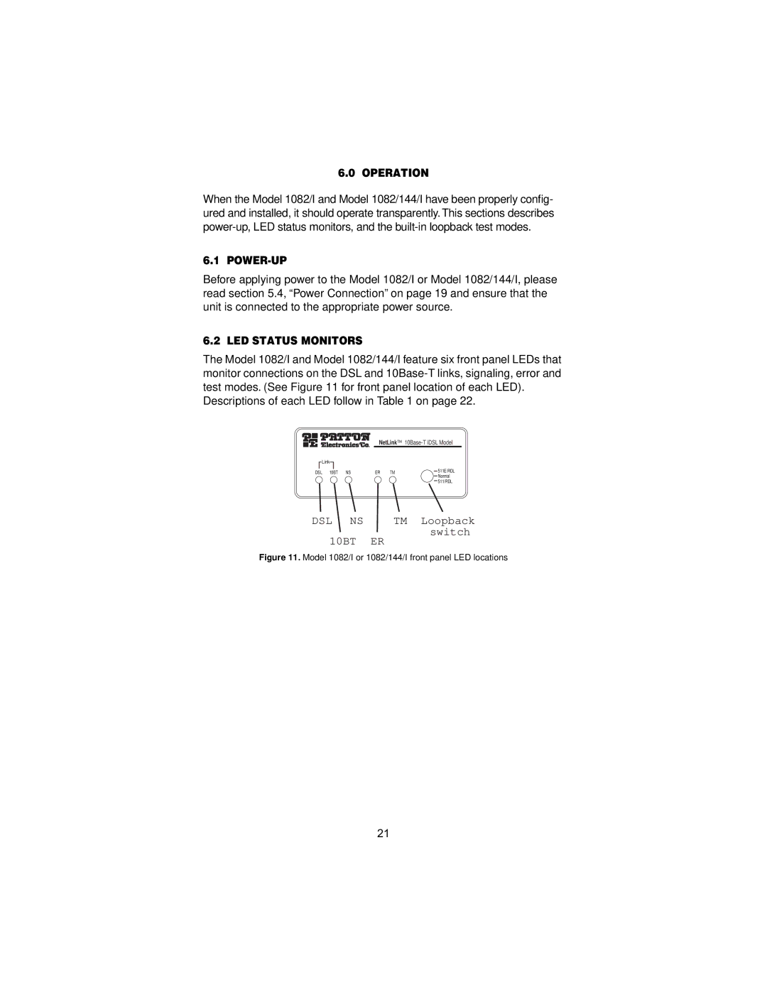
The Model 1082/I and Model 1082/144/I feature six front panel LEDs that monitor connections on the DSL and
Descriptions of each LED follow in Table 1 on page 22.
NetLink™
Link |
|
|
|
|
DSL 10BT | NS | ER | TM | 511E/RDL |
|
|
|
| Normal |
|
|
|
| 511/RDL |
DSL NS | TM Loopback |
10BT | switch |
ER |
Figure 11. Model 1082/I or 1082/144/I front panel LED locations
21