4.0 CONFIGURATION
The Model 1082/I and Model 1082/144/I each are equipped with 16 DIP switches that enable configuration of the unit for a wide variety of appli- cations. This section describes switch locations and explains the different configurations.
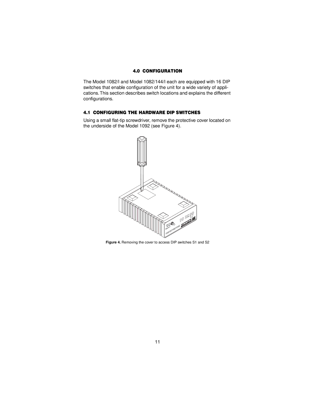
4.1 CONFIGURING THE HARDWARE DIP SWITCHES
Using a small
|
|
|
|
|
|
|
| DSL |
|
|
|
|
|
| Status | 10BT | |
|
|
|
|
|
| Link | ||
|
|
|
|
|
| NS . | G | Model |
|
|
|
|
|
|
| ||
|
|
| ER | 704 | . | 703/G | 1194E | |
| 511E |
|
| |||||
| TM | Test |
|
| Single |
| ||
511/RDL |
| Modes |
|
|
|
| ||
| Mode |
|
|
|
| |||
511 |
|
|
|
|
| |||
Normal | Fiber |
|
|
|
|
| ||
| - |
|
|
|
|
|
| |
511E/RBL |
| QuadNetLink |
|
|
|
|
|
|
| .G |
|
|
|
|
|
| |
| 703/G10BastT |
|
|
|
|
|
| |
iDSL704. |
|
|
|
|
|
|
| |
mMode |
|
|
|
|
|
|
|
|
Figure 4. Removing the cover to access DIP switches S1 and S2
11