Chapter 2 InstallationIPmux-16Installation and Operation Manual
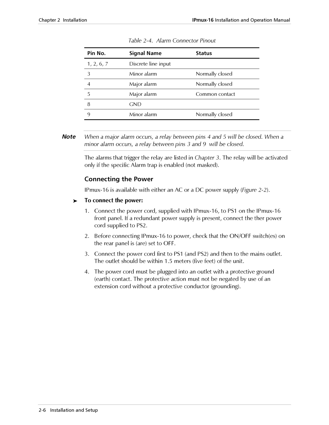
Table 2-4. Alarm Connector Pinout
Pin No. | Signal Name | Status |
|
|
|
1, 2, 6, 7 | Discrete line input |
|
|
|
|
3 | Minor alarm | Normally closed |
|
|
|
4 | Major alarm | Normally closed |
|
|
|
5 | Major alarm | Common contact |
|
|
|
8 | GND |
|
|
|
|
9 | Minor alarm | Normally closed |
|
|
|
Note When a major alarm occurs, a relay between pins 4 and 5 will be closed. When a minor alarm occurs, a relay between pins 3 and 9 will be closed.
The alarms that trigger the relay are listed in Chapter 3. The relay will be activated only if the specific Alarm trap is enabled (not masked).
Connecting the Power
➤To connect the power:
1.Connect the power cord, supplied with
2.Before connecting
3.Connect the power cord first to PS1 (and PS2) and then to the mains outlet. The outlet should be within 1.5 meters (five feet) of the unit.
4.The power cord must be plugged into an outlet with a protective ground (earth) contact. The protective action must not be negated by use of an extension cord without a protective conductor (grounding).