Chapter 3 Operation | |
|
|
Alarms Trap Mask
Main menu
↓
2.Configuration
↓
1.General Configuration
↓
3.Management Configuration
↓
5.Alarms Trap Mask
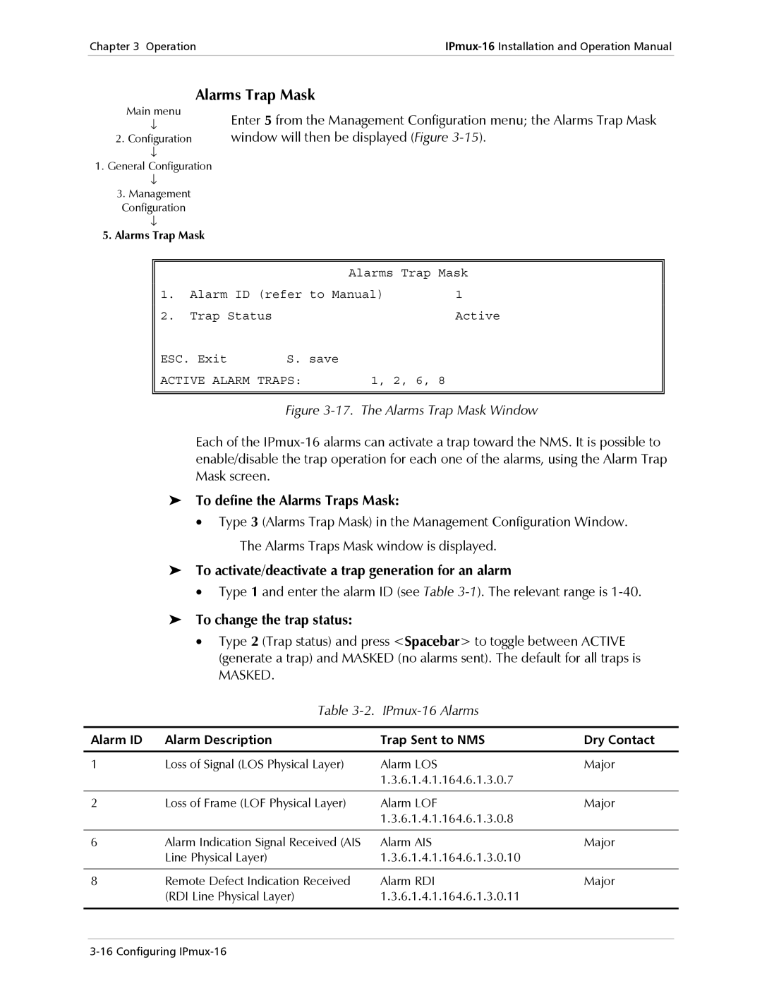
Enter 5 from the Management Configuration menu; the Alarms Trap Mask window will then be displayed (Figure
|
|
| Alarms Trap Mask | |
1. | Alarm ID (refer to Manual) | 1 | ||
2. | Trap Status |
|
| Active |
ESC. Exit | S. save |
|
| |
ACTIVE ALARM TRAPS: | 1, 2, 6, 8 |
| ||
|
|
|
|
|
|
|
|
|
|
Figure 3-17. The Alarms Trap Mask Window
Each of the
➤To define the Alarms Traps Mask:
• Type 3 (Alarms Trap Mask) in the Management Configuration Window.
The Alarms Traps Mask window is displayed.
➤To activate/deactivate a trap generation for an alarm
•Type 1 and enter the alarm ID (see Table
➤To change the trap status:
•Type 2 (Trap status) and press <Spacebar> to toggle between ACTIVE (generate a trap) and MASKED (no alarms sent). The default for all traps is
MASKED.
| Table |
|
|
|
|
|
|
Alarm ID | Alarm Description | Trap Sent to NMS | Dry Contact |
|
|
|
|
1 | Loss of Signal (LOS Physical Layer) | Alarm LOS | Major |
|
| 1.3.6.1.4.1.164.6.1.3.0.7 |
|
|
|
|
|
2 | Loss of Frame (LOF Physical Layer) | Alarm LOF | Major |
|
| 1.3.6.1.4.1.164.6.1.3.0.8 |
|
|
|
|
|
6 | Alarm Indication Signal Received (AIS | Alarm AIS | Major |
| Line Physical Layer) | 1.3.6.1.4.1.164.6.1.3.0.10 |
|
|
|
|
|
8 | Remote Defect Indication Received | Alarm RDI | Major |
| (RDI Line Physical Layer) | 1.3.6.1.4.1.164.6.1.3.0.11 |
|
|
|
|
|
