Chapter 1 Introduction | |
|
|
•Adaptive: In this mode, the E1 or T1 Tx clock is regenerated using the Adaptive method. In this method, the fill level of the buffer receiving packets is monitored. If the buffer begins to overfill, the regenerated clock frequency increases to avoid overflow. If the buffer begins to empty, the clock decreases to avoid underflow.
•Internal Clock: In this mode, the Transmit (Tx) clock is received from an internal oscillator. This mode is useful for testing and diagnostic purposes.
Each of the clocks must be configured correctly on both the Receive and Transmit ends to ensure proper operation and prevent pattern slips.
The following paragraphs describe typical timing schemes and their correct timing mode settings in order to achieve
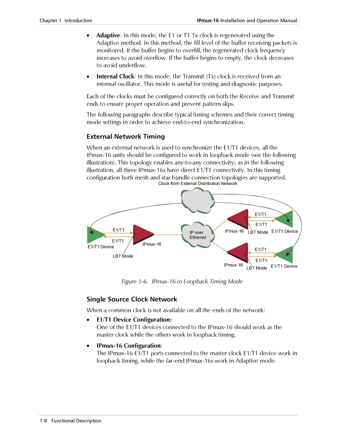
External Network Timing
When an external network is used to synchronize the E1/T1 devices, all the
Clock from External Distribution Network
|
|
|
|
| E1/T1 |
|
E1/T1 |
|
|
|
| E1/T1 |
|
|
| IP over | LBT Mode | E1/T1 Device | ||
E1/T1 |
|
| Ethernet |
|
|
|
|
|
| ||||
E1/T1 Device |
| E1/T1 |
| |||
|
|
|
|
| ||
|
|
|
|
|
| |
LBT Mode |
|
|
|
| E1/T1 |
|
|
|
|
| E1/T1 Device | ||
|
|
|
| LBT Mode | ||
Figure 1-6. IPmux-16 in Loopback Timing Mode
Single Source Clock Network
When a common clock is not available on all the ends of the network:
•E1/T1 Device Configuration:
One of the E1/T1 devices connected to the
•IPmux-16 Configuration:
The