Chapter 3
Operation
3.1 Introduction
This chapter gives a detailed description of the front panel controls and indicators and their functions, explains
3.2 Front Panel Controls, Connectors, and Indicators
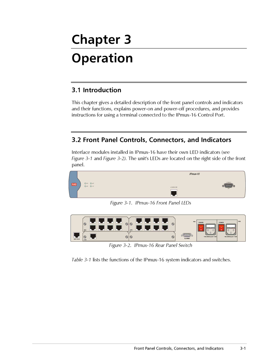
Interface modules installed in
Figure 3-1 and Figure 3-2). The unit's LEDs are located on the right side of the front panel.
Figure 3-1. IPmux-16 Front Panel LEDs
PS1 | POWER | PS2 |
| POWER | |
| I | I |
| O | O |
| 3A T 125V |
EXT. CLK | ALARMS |
Figure 3-2. IPmux-16 Rear Panel Switch
Table
Front Panel Controls, Connectors, and Indicators |