Table 2-1. Null Cable Pinout Connections
| Signal | Name |
Pin No. |
|
|
|
|
|
1 | DCD | Data Carrier Detect |
|
|
|
2 | RXD | Receive data |
|
|
|
3 | TXD | Transmit data |
|
|
|
4 | DTR | Data Terminal Ready |
|
|
|
5 | GND | Ground |
|
|
|
6 | DSR | Data Set Ready |
|
|
|
7 | RTS | Request To Send |
|
|
|
8 | CTS | Clear To Send |
|
|
|
9 | RI | Ring Indicator |
|
|
|
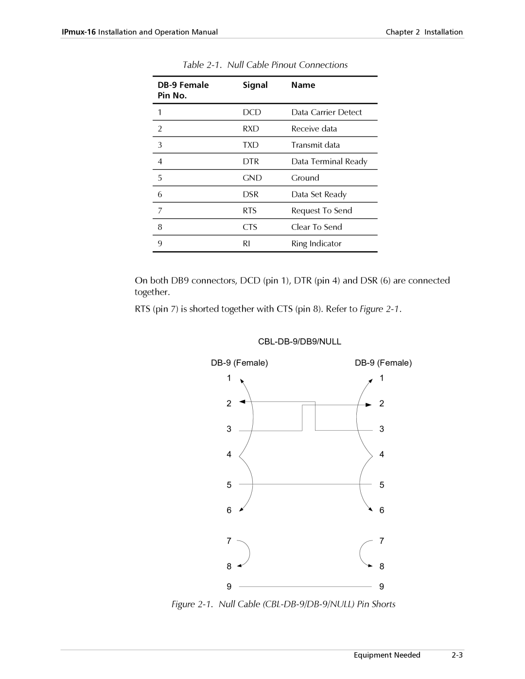
On both DB9 connectors, DCD (pin 1), DTR (pin 4) and DSR (6) are connected together.
RTS (pin 7) is shorted together with CTS (pin 8). Refer to Figure
2
3
4
5
6
7
8
9
2
3
4
5
6
7
8
9
Figure 2-1. Null Cable (CBL-DB-9/DB-9/NULL) Pin Shorts
Equipment Needed |