Chapter 2 Installation | |
|
|
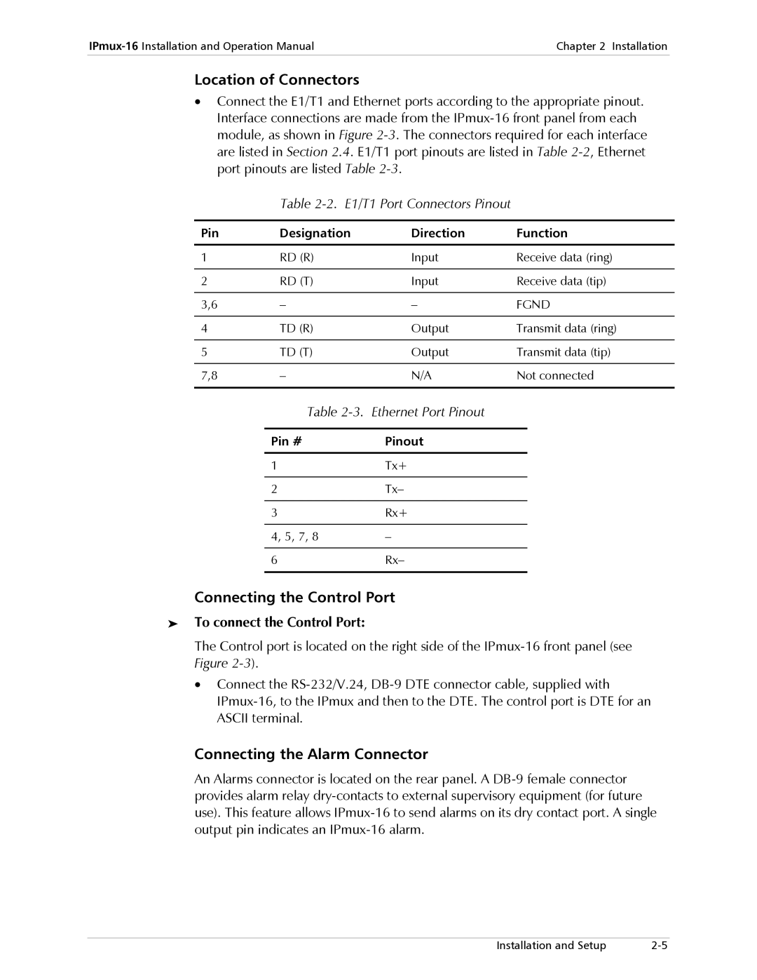
Location of Connectors
•Connect the E1/T1 and Ethernet ports according to the appropriate pinout. Interface connections are made from the
Table 2-2. E1/T1 Port Connectors Pinout
Pin | Designation | Direction | Function |
|
|
|
|
1 | RD (R) | Input | Receive data (ring) |
|
|
|
|
2 | RD (T) | Input | Receive data (tip) |
|
|
|
|
3,6 | – | – | FGND |
|
|
|
|
4 | TD (R) | Output | Transmit data (ring) |
|
|
|
|
5 | TD (T) | Output | Transmit data (tip) |
|
|
|
|
7,8 | – | N/A | Not connected |
|
|
|
|
Table
Pin # | Pinout |
|
|
1 | Tx+ |
|
|
2 | Tx– |
|
|
3 | Rx+ |
|
|
4, 5, 7, 8 | – |
|
|
6 | Rx– |
|
|
Connecting the Control Port
➤To connect the Control Port:
The Control port is located on the right side of the
•Connect the
Connecting the Alarm Connector
An Alarms connector is located on the rear panel. A
Installation and Setup |