Chapter 1 Introduction | |
|
|
Front Panel
The control port and indicator LEDs are located on the front panel of
Rear Panel
Fuses, power supplies, the dry contact connector, and interface connectors are located on the rear panel of
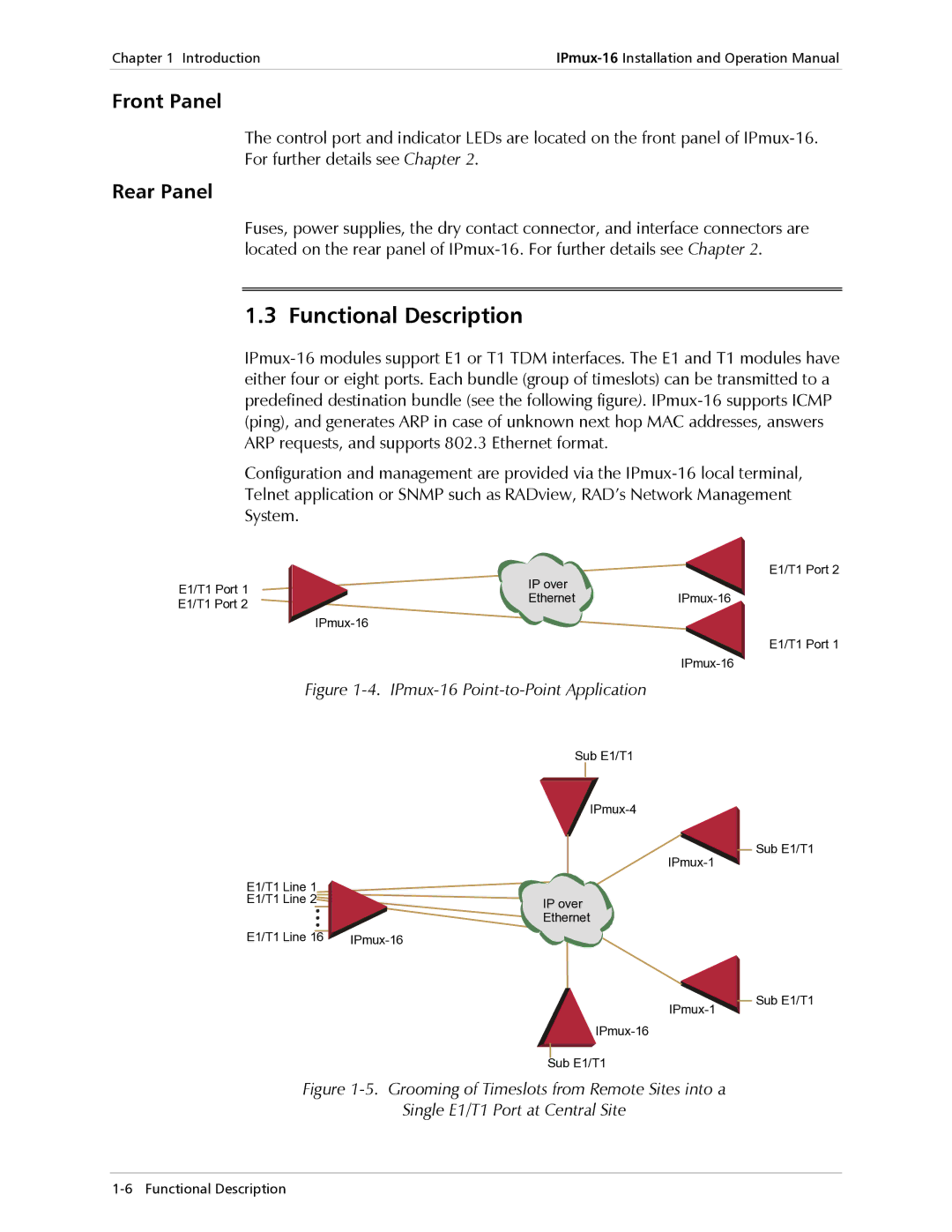
1.3 Functional Description
Configuration and management are provided via the
E1/T1 Port 1 | IP over |
| |
Ethernet | |||
E1/T1 Port 2 | |||
|
| ||
|
| ||
|
|
Figure 1-4. IPmux-16 Point-to-Point Application
Sub E1/T1
E1/T1 Line 1 |
|
E1/T1 Line 2 | IP over |
| Ethernet |
E1/T1 Line 16 |
Sub E1/T1
Figure 1-5. Grooming of Timeslots from Remote Sites into a
Single E1/T1 Port at Central Site
E1/T1 Port 2
E1/T1 Port 1
Sub E1/T1
Sub E1/T1