5.0 OPERATION
Once the Model 1068s are properly installed, they should operate trans- parently. No user settings required. This section describes reading the LED status monitors.
5.1 POWER UP
Before applying power to the Model 1068, please review section 3.6, “Connecting Power” on page 14 to verify that the unit is connected to the appropriate power source.
5.2 FRONT PANEL LED STATUS MONITORS
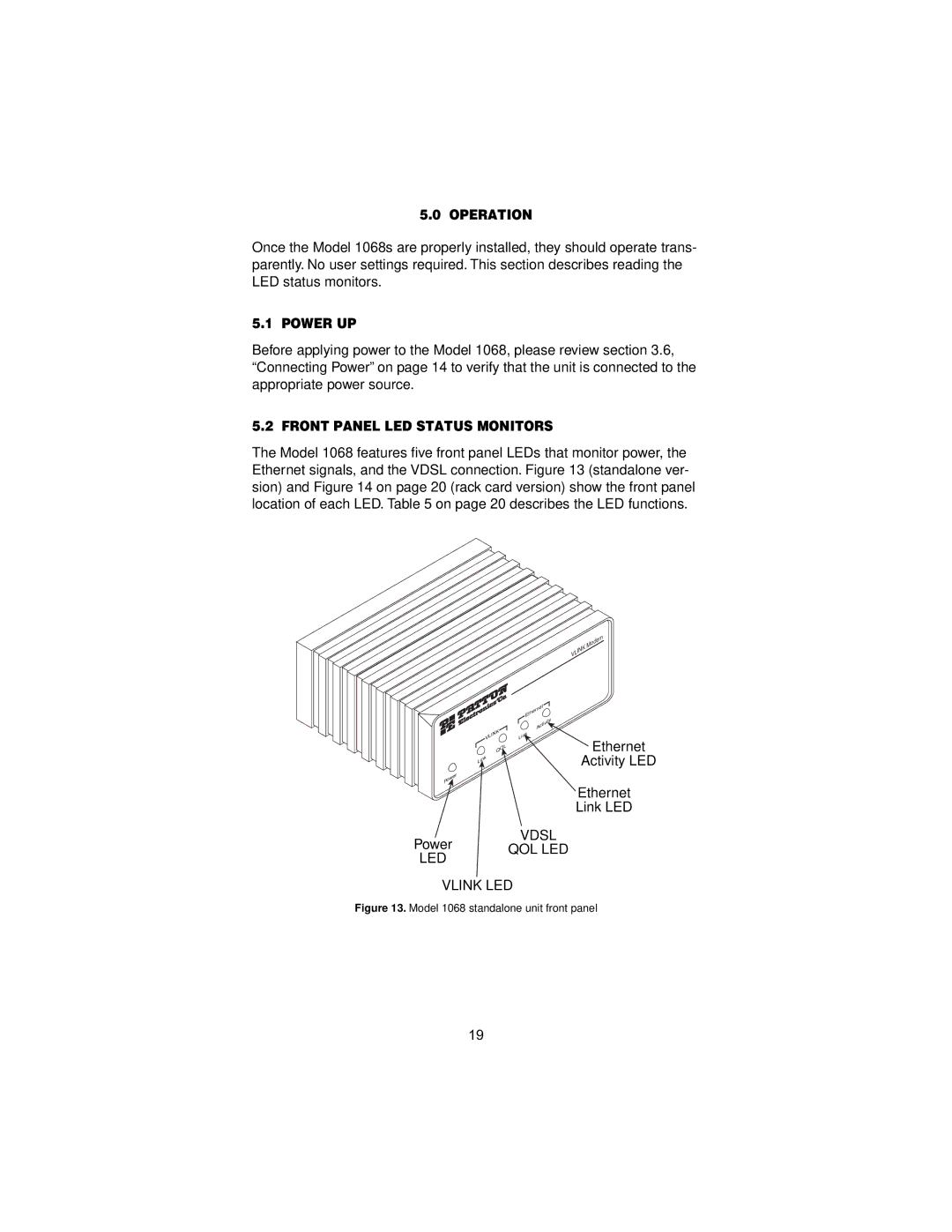
The Model 1068 features five front panel LEDs that monitor power, the Ethernet signals, and the VDSL connection. Figure 13 (standalone ver- sion) and Figure 14 on page 20 (rack card version) show the front panel location of each LED. Table 5 on page 20 describes the LED functions.
Modem
VLINK
Ethernet
VLINK | Link |
QOL |
|
Link
Activity
![]() Ethernet Activity LED
Ethernet Activity LED
Power
Ethernet
Link LED
VDSL
Power QOL LED
LED
VLINK LED
Figure 13. Model 1068 standalone unit front panel
19