Model 2960/2996 RAS User Manual

5 • Troubleshooting and maintenance


Fault analysis

The following procedures outline steps you should follow when troubleshooting a RAS malfunction.

1.If possible, talk to the person who filed the trouble complaint and determine the operational symptoms. Record the symptoms on the appropriate trouble report form (include the front panel LED indications).

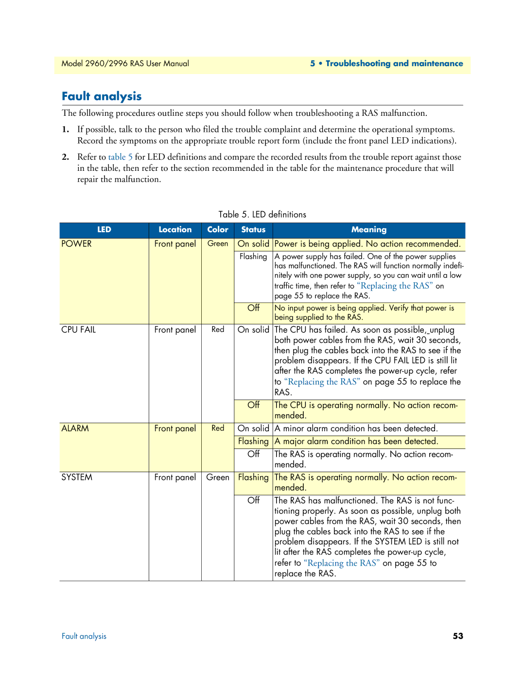
2.Refer to table 5 for LED definitions and compare the recorded results from the trouble report against those in the table, then refer to the section recommended in the table for the maintenance procedure that will repair the malfunction.

Table 5. LED definitions

LED

Location

Color Status

Meaning


POWER

Front panel

Green

On solid

Power is being applied. No action recommended.


Flashing

A power supply has failed. One of the power supplies


has malfunctioned. The RAS will function normally indefi-


nitely with one power supply, so you can wait until a low


traffic time, then refer to “Replacing the RAS” on


page 55 to replace the RAS.


Off

No input power is being applied. Verify that power is


being supplied to the RAS.

CPU FAIL

Front panel

Red

On solid

The CPU has failed. As soon as possible, unplug


both power cables from the RAS, wait 30 seconds,


then plug the cables back into the RAS to see if the


problem disappears. If the CPU FAIL LED is still lit


after the RAS completes the power-up cycle, refer


to “Replacing the RAS” on page 55 to replace the


RAS.


Off

The CPU is operating normally. No action recom-


mended.

ALARM

Front panel

Red

On solid

A minor alarm condition has been detected.


Flashing

A major alarm condition has been detected.


Off

The RAS is operating normally. No action recom-


mended.

SYSTEM

Front panel

Green

Flashing

The RAS is operating normally. No action recom-


mended.


Off

The RAS has malfunctioned. The RAS is not func-


tioning properly. As soon as possible, unplug both


power cables from the RAS, wait 30 seconds, then


plug the cables back into the RAS to see if the


problem disappears. If the SYSTEM LED is still not


lit after the RAS completes the power-up cycle,


refer to “Replacing the RAS” on page 55 to


replace the RAS.

Fault analysis

53

Page 53
Image 53
Patton electronic 2960, 2996 user manual Fault analysis, Power

2960, 2996 specifications

The Patton Electronics 2996 and 2960 series encapsulates a line of robust communication devices designed for versatile applications in data transmission and connectivity. These models cater to various industries, providing reliable performance, ease of use, and advanced features.

The Patton 2996 is known for its adeptness at functioning as a high-speed T1/E1 access device, making it ideal for businesses seeking efficient integration into existing networks. With a dual-channel design, the 2996 can support multiple voice and data streams simultaneously, facilitating seamless communication. Enhanced with built-in diagnostics and a user-friendly web interface, network administrators can easily monitor performance and configuration settings.

On the other hand, the Patton 2960 series includes HD voice gateway features, allowing users to connect legacy telephone systems with VoIP networks. This series stands out with its ability to support a myriad of protocols, such as SIP and H.323, ensuring compatibility with various telecommunication standards. By bridging traditional telephony with modern IP networks, the 2960 fosters an adaptable and scalable communication environment for businesses of all sizes.

Both models are equipped with comprehensive security features, including robust encryption protocols, ensuring that data remains protected during transmission. Additionally, they support Quality of Service (QoS) parameters to prioritize voice traffic, minimizing latency and enhancing the clarity of calls.

The hardware design of the Patton 2996 and 2960 series emphasizes reliability and durability. With solid construction, these devices are engineered to withstand challenging conditions, making them suitable for deployment in diverse environments. The easy installation process, coupled with wide-ranging support for various interfaces, ensures they can integrate smoothly with existing infrastructure.

In summary, the Patton Electronics 2996 and 2960 series represent high-quality communication solutions that blend advanced technology with practical features. Their capabilities to support both legacy and modern systems make them invaluable assets for any organization looking to enhance its communication effectiveness and efficiency. Whether it's for data transmission or voice gateway functionality, these models deliver reliable performance and a range of features tailored to meet the demands of today’s ever-evolving connectivity landscape.