5.0 OPERATION
Once you have configured each Model 1065 Series unit properly and connected the twisted pair and
5.1 LED STATUS MONITORS
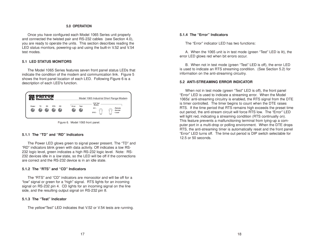
The Model 1065 Series features seven front panel status LEDs that indicate the condition of the modem and communication link. Figure 5 shows the front panel location of each LED. Following Figure 6 is a description of each LED's function.
Model 1065 Industrial Short Range Modem
|
|
|
|
|
| V.54 Test |
| |
Power | TX | RX | RTS | CD | Error | Modes |
| |
Test |
|
| ||||||
|
|
|
|
|
| 511 | - | - Remote |
|
|
|
|
|
|
|
| - Normal |
|
|
|
|
|
| 511E | - | - Local |
Figure 6. Model 1065 front panel.
5.1.1 The “TD” and “RD” Indicators
The Power LED glows green to signal power present. The “TD” and “RD” indicators blink green with data activity. Off indicates a low RS- 232 logic level, green indicates a high
5.1.2 The “RTS” and “CD” Indicators
The “RTS” and “CD” indicators are monocolor and will be off for a “low” signal or green for a “high” signal. RTS lights for an incoming signal on
5.1.3 The “Test” Indicator
The yellow“Test” LED indicates that V.52 or V.54 tests are running.
5.1.4 The “Error” Indicators
The “Error” indicator LED has two functions:
A.When the 1065 unit is in test mode (green “Test” LED is lit), the error LED glows red when bit errors occur.
B.When not in test mode (green “Test” LED is off), the error LED is used to indicate an RTS streaming condition. (See Section 5.2) for information on the
5.2ANTI-STREAMING ERROR INDICATOR
When not in test mode (green “Test” LED is off), the front panel “Error” LED is used to indicate a streaming error. When the Model 1065s’
17 | 18 |