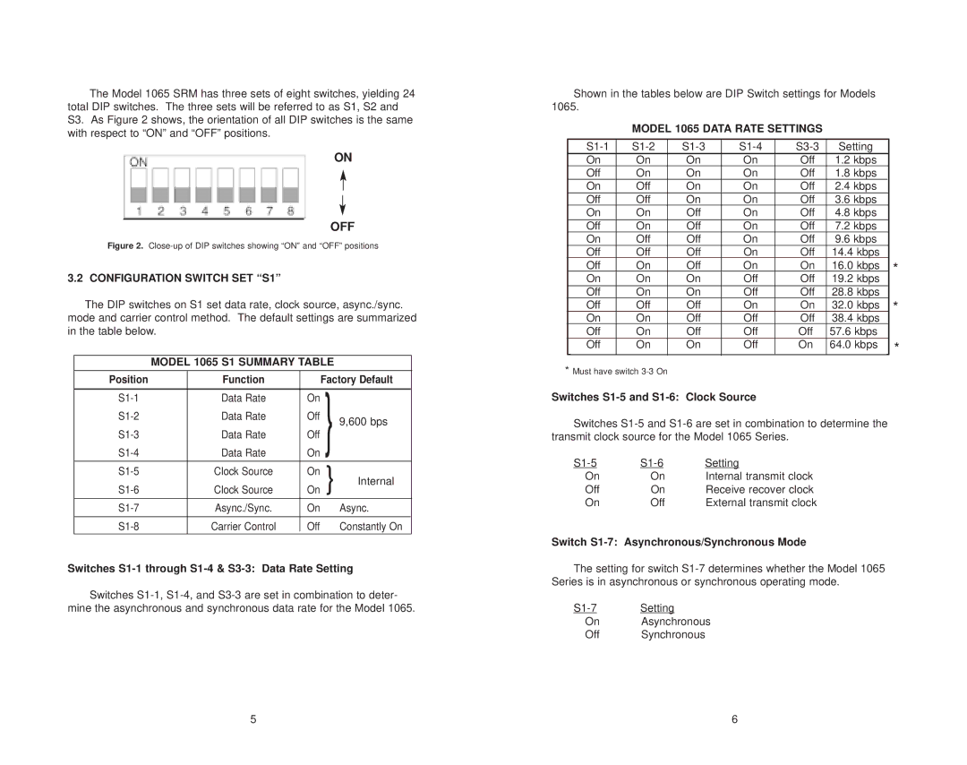
The Model 1065 SRM has three sets of eight switches, yielding 24 total DIP switches. The three sets will be referred to as S1, S2 and
S3. As Figure 2 shows, the orientation of all DIP switches is the same with respect to “ON” and “OFF” positions.
ON
OFF
Figure 2. Close-up of DIP switches showing “ON” and “OFF” positions
3.2 CONFIGURATION SWITCH SET “S1”
The DIP switches on S1 set data rate, clock source, async./sync. mode and carrier control method. The default settings are summarized in the table below.
MODEL 1065 S1 SUMMARY TABLE
Position | Function |
| Factory Default |
| |
|
|
|
|
|
|
Data Rate | On | } |
|
| |
Data Rate | Off | 9,600 bps |
| ||
|
|
|
| ||
Data Rate | Off |
|
| ||
Data Rate | On |
|
| ||
Clock Source | On | } | Internal |
| |
Clock Source | On |
| |||
Async./Sync. | On |
| Async. |
| |
|
|
|
|
|
|
Carrier Control | Off |
| Constantly On |
| |
|
|
|
|
|
|
Switches S1-1 through S1-4 & S3-3: Data Rate Setting
Switches
Shown in the tables below are DIP Switch settings for Models 1065.
|
| MODEL 1065 DATA RATE SETTINGS |
|
|
| |||
| Setting |
|
| |||||
| On | On | On | On | Off | 1.2 kbps |
|
|
| Off | On | On | On | Off | 1.8 kbps |
|
|
| On | Off | On | On | Off | 2.4 kbps |
|
|
| Off | Off | On | On | Off | 3.6 kbps |
|
|
| On | On | Off | On | Off | 4.8 kbps |
|
|
| Off | On | Off | On | Off | 7.2 kbps |
|
|
| On | Off | Off | On | Off | 9.6 kbps |
|
|
| Off | Off | Off | On | Off | 14.4 kbps |
|
|
| Off | On | Off | On | On | 16.0 kbps |
| * |
| On | On | On | Off | Off | 19.2 kbps |
| |
|
|
| ||||||
| Off | On | On | Off | Off | 28.8 kbps |
|
|
| Off | Off | Off | On | On | 32.0 kbps |
| * |
| On | On | Off | Off | Off | 38.4 kbps |
| |
|
|
| ||||||
| Off | On | Off | Off | Off | 57.6 kbps |
|
|
| Off | On | On | Off | On | 64.0 kbps |
| * |
*Must have switch
Switches S1-5 and S1-6: Clock Source
Switches
Setting | ||
On | On | Internal transmit clock |
Off | On | Receive recover clock |
On | Off | External transmit clock |
Switch S1-7: Asynchronous/Synchronous Mode
The setting for switch
Setting | |
On | Asynchronous |
Off | Synchronous |
5 | 6 |