Switch S3-5: RS-232 Initiation of Local Loopback Test
The setting for switch S3-5 determines whether or not the Model 1065 local analog loopback test can be initiated by raising pin 18 on the RS-232 interface.
S3-5 | Setting |
On | RS-232 initiation enabled |
Off | RS-232 initiation disabled |
Switch S3-6: RS-232 Initiation of Remote Loopback Test
The setting for switch S3-6 determines whether or not the Model 1065 remote digital loopback test can be initiated by raising pin 21 on the RS-232 interface.
S3-6 | Setting |
On | RS-232 initiation enabled |
Off | RS-232 initiation disabled |
Switches S3-7 and S3-8: Anti-stream Control
Switches S3-7 and S3-8 are set in combination to determine the time out period for the Model 1065 Series’ anti-stream control timer.
S3-7 | S3-8 | Setting |
Off | Off | Disabled |
Off | On | 12.5 seconds |
On | Off | 50.0 seconds |
On | On | 12.5 seconds |
4.0 INSTALLATION
The Model 1065 operates in four twisted pair topologies: 2-wire/point-to-point, 2-wire/multipoint, 4-wire/point-to-point, and
4-wire/multipoint. In each of these topologies, the twisted pair wire must be 19 - 26 AWG "dry", unconditioned metallic wire (see Appendix C for wire recommendations). Dial-up analog circuits, such as those used with a standard Hayes-type modem, are not acceptable. The twisted pair may be shielded or unshielded. Both types yield favorable results.
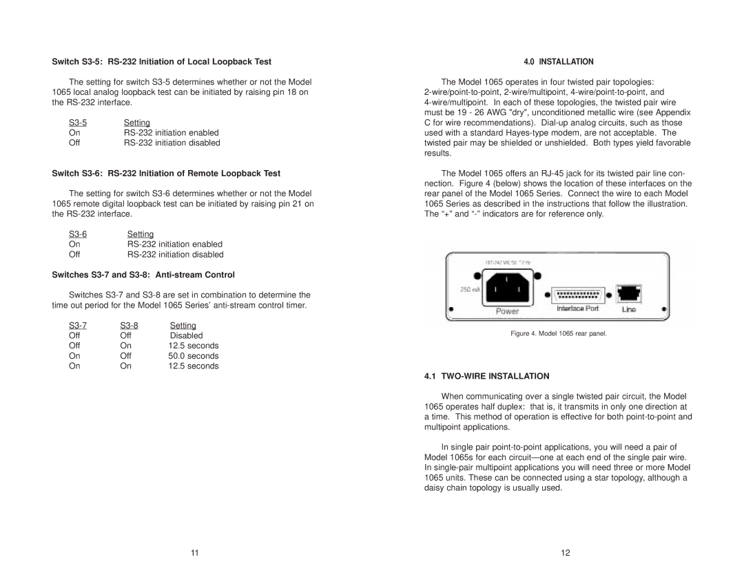
The Model 1065 offers an RJ-45 jack for its twisted pair line con- nection. Figure 4 (below) shows the location of these interfaces on the rear panel of the Model 1065 Series. Connect the wire to each Model 1065 Series as described in the instructions that follow the illustration. The “+” and “-” indicators are for reference only.
Figure 4. Model 1065 rear panel.
4.1 TWO-WIRE INSTALLATION
When communicating over a single twisted pair circuit, the Model 1065 operates half duplex: that is, it transmits in only one direction at a time. This method of operation is effective for both point-to-point and multipoint applications.
In single pair point-to-point applications, you will need a pair of Model 1065s for each circuit—one at each end of the single pair wire. In single-pair multipoint applications you will need three or more Model 1065 units. These can be connected using a star topology, although a daisy chain topology is usually used.

