Switch S1-8: Carrier Control Method
The setting for switch
Setting | |
Off | Constantly on |
On | Controlled by RTS |
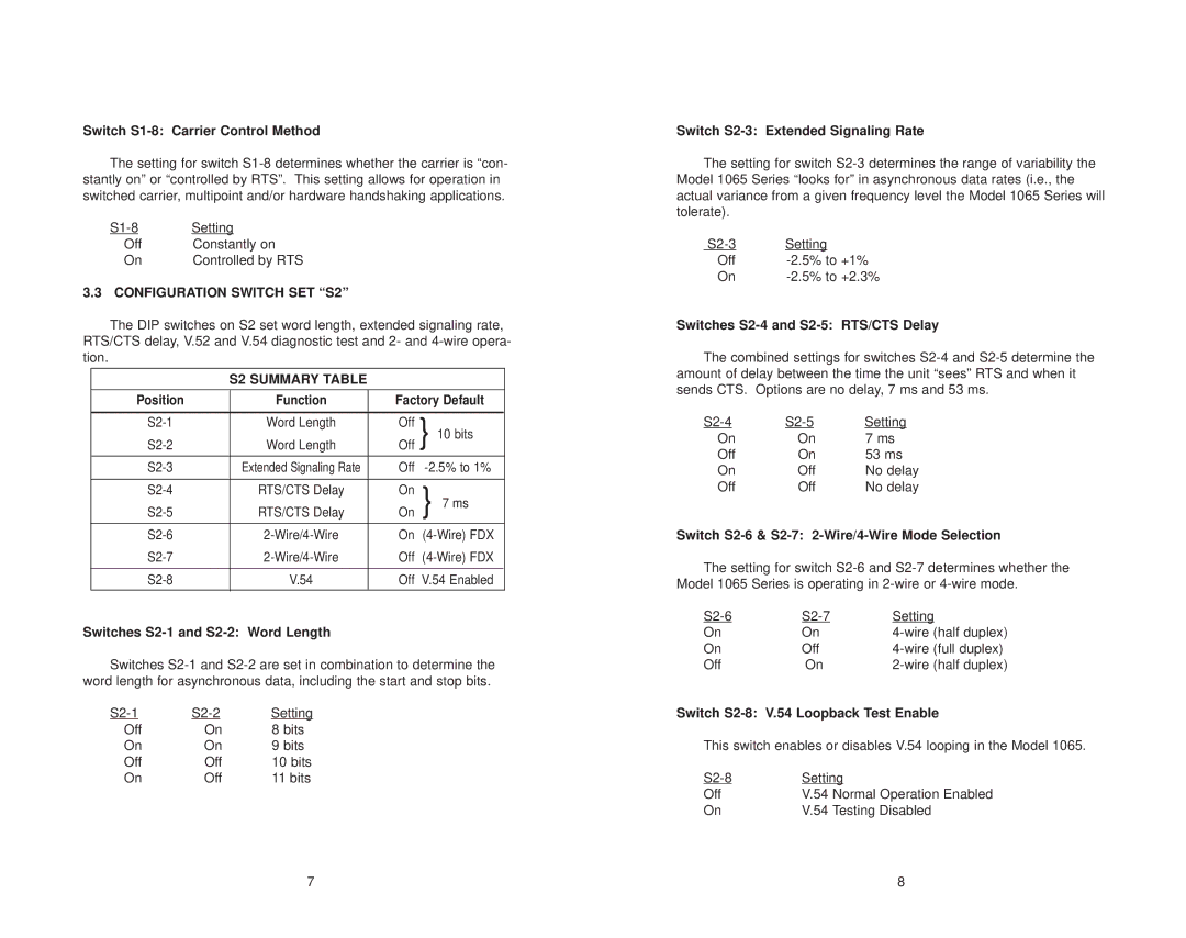
3.3 CONFIGURATION SWITCH SET “S2”
The DIP switches on S2 set word length, extended signaling rate, RTS/CTS delay, V.52 and V.54 diagnostic test and 2- and
S2 SUMMARY TABLE
Position | Function | Factory Default | ||
|
|
|
|
|
Word Length | Off | } 10 bits | ||
Word Length | Off | |||
|
|
|
|
|
Extended Signaling Rate | Off | |||
|
|
|
|
|
RTS/CTS Delay | On | } 7 ms | ||
RTS/CTS Delay | On | |||
|
|
|
|
|
On | ||||
Off | ||||
|
|
|
|
|
V.54 | Off | V.54 Enabled | ||
|
|
|
|
|
Switches S2-1 and S2-2: Word Length
Switches
Setting | ||
Off | On | 8 bits |
On | On | 9 bits |
Off | Off | 10 bits |
On | Off | 11 bits |
Switch S2-3: Extended Signaling Rate
The setting for switch
Setting | |
Off | |
On |
Switches S2-4 and S2-5: RTS/CTS Delay
The combined settings for switches
Setting | ||
On | On | 7 ms |
Off | On | 53 ms |
On | Off | No delay |
Off | Off | No delay |
Switch S2-6 & S2-7: 2-Wire/4-Wire Mode Selection
The setting for switch
Setting | ||
On | On | |
On | Off | |
Off | On |
Switch S2-8: V.54 Loopback Test Enable
This switch enables or disables V.54 looping in the Model 1065.
Setting | ||
Off | V.54 | Normal Operation Enabled |
On | V.54 | Testing Disabled |
7 | 8 |