2.0 GENERAL INFORMATION
Thank you for your purchase of this Patton Electronics product. This product has been thoroughly inspected by Patton's qualified tech- nicians. If any questions or problems arise during installation or use of this product, please do not hesitate to contact Patton Electronics Technical Support at (301)
2.1FEATURES
•Synchronous or asynchronous operation
•Model 1065 supports data rates up to 64.0 kbps
•
•V.52 & V.54 test modes
•Equalization
•
•Distances up to 12 miles (19.2 km)
•
•Internal, external or received loopback clocking
•2000 VAC transformer isolation & high speed surge protection
•Internal power supply
•
2.2DESCRIPTION
The Model 1065 Industrial Short Range Modem operates
The Model 1065 has several features to enhance overall perform- ance: equalization,
The Model 1065 features V.52 compliant bit error rate pattern tests and two V.54 test modes: local analog loopback and remote digital loopback. The operator at the local end may test both local and remote modems, plus the line, in the digital loopback mode. Both RDL and LAL modes can be controlled by a manual switch or via the
3.0 CONFIGURATION OVERVIEW
The Model 1065 is fairly simple to install and is ruggedly designed for excellent reliability: just set it and forget it. The following instruc- tions will help you set up and install the Model 1065 properly.
3.1 CONFIGURATION SWITCHES
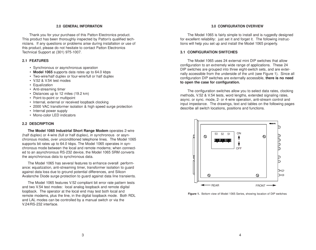
The Model 1065 uses 24 external mini DIP switches that allow configuration to an extremely wide range of applications. These 24 DIP switches are grouped into three
The configuration switches allow you to select data rates, clocking methods, V.52 & V.54 tests, word lengths, extended signaling rates, async. or sync. mode, 2- or
S3 |
| S2 |
| S1 |
| ON |
|
|
|
|
|
|
|
|
|
|
|
|
|
|
OFF
REAR | FRONT |
|
|
|
| ||
|
|
|
|
Figure 1. Bottom view of Model 1065 Series, showing location of DIP switches
3 | 4 |