4.1.1Two-Wire Cable Connection Via RJ-45

A. The RJ-45 jack on a Model 1065 Series Short Range Modem is prewired for a standard TELCO wiring environment. To be sure you have the right wiring, use the table below as a guide.

RJ-45 SIGNAL

1-------------NC

2-------------GND

3-------------RCV

4-------------XMT

5-------------XMT

6-------------RCV

7-------------GND

8-------------NC

Connection to ground is optional

B. Proper wiring of pairs between the two modems is as follows:

SIGNAL

PIN#

COLOR*

COLOR

PIN#

SIGNAL

XMT

4

Green ------------

Green

4

XMT

XMT

5

Red ---------------

Red

5

XMT

*Standard color codes—yours may be different

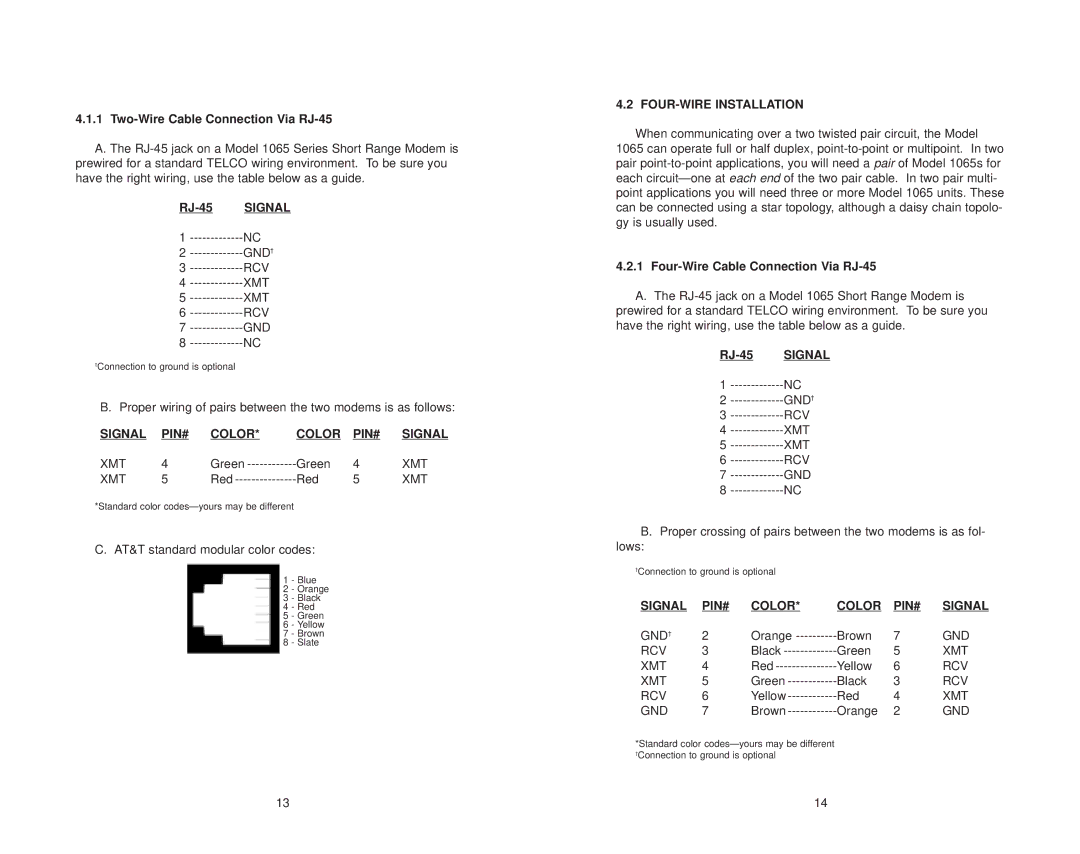
C. AT&T standard modular color codes:

1 - Blue

2 - Orange

3 - Black

4 - Red

5 - Green

6 - Yellow

7 - Brown

8 - Slate

4.2 FOUR-WIRE INSTALLATION

When communicating over a two twisted pair circuit, the Model 1065 can operate full or half duplex, point-to-point or multipoint. In two pair point-to-point applications, you will need a pair of Model 1065s for each circuit—one at each end of the two pair cable. In two pair multi- point applications you will need three or more Model 1065 units. These can be connected using a star topology, although a daisy chain topolo- gy is usually used.

4.2.1Four-Wire Cable Connection Via RJ-45

A. The RJ-45 jack on a Model 1065 Short Range Modem is prewired for a standard TELCO wiring environment. To be sure you have the right wiring, use the table below as a guide.

RJ-45 SIGNAL

1-------------NC

2-------------GND

3-------------RCV

4-------------XMT

5-------------XMT

6-------------RCV

7-------------GND

8-------------NC

B. Proper crossing of pairs between the two modems is as fol- lows:

Connection to ground is optional

SIGNAL

PIN#

COLOR*

COLOR

PIN#

SIGNAL

GND

2

Orange ----------

Brown

7

GND

RCV

3

Black -------------

Green

5

XMT

XMT

4

Red ---------------

Yellow

6

RCV

XMT

5

Green ------------

Black

3

RCV

RCV

6

Yellow ------------

Red

4

XMT

GND

7

Brown ------------

Orange

2

GND

*Standard color codes—yours may be different

Connection to ground is optional

13

14

Page 8
Image 8
Patton electronic Model 1065 Two-Wire Cable Connection Via RJ-45, RJ-45 Signal, Signal PIN# Color, FOUR-WIRE Installation