Patton electronic Model 1065 user manual FOUR-WIRE, Multipoint Installation, RS-232 Connection

Models: Model 1065

1 13
Download 13 pages 16.71 Kb
Page 9
Image 9

C. AT&T standard modular color codes:

1 - Blue

2 - Orange

3 - Black

4 - Red

5 - Green

6 - Yellow

7 - Brown

8 - Slate

4.3 FOUR-WIRE, MULTIPOINT INSTALLATION

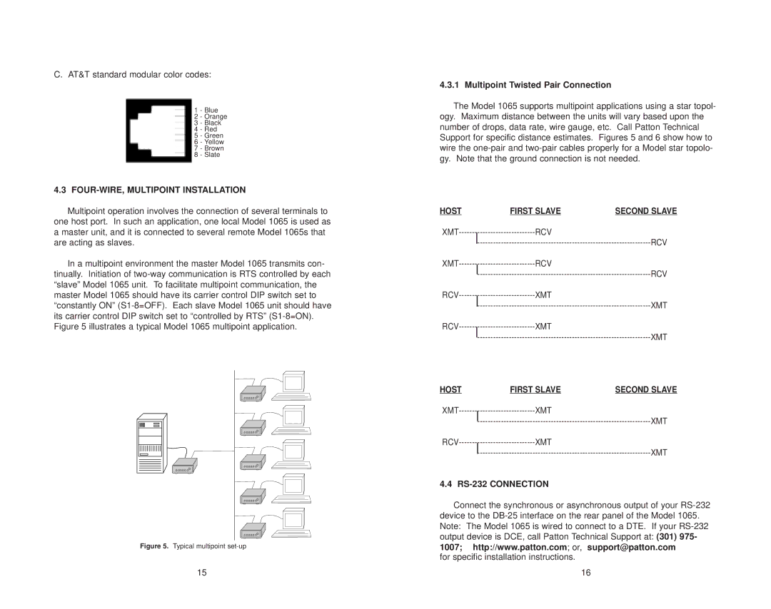
Multipoint operation involves the connection of several terminals to one host port. In such an application, one local Model 1065 is used as a master unit, and it is connected to several remote Model 1065s that are acting as slaves.

In a multipoint environment the master Model 1065 transmits con- tinually. Initiation of two-way communication is RTS controlled by each “slave” Model 1065 unit. To facilitate multipoint communication, the master Model 1065 should have its carrier control DIP switch set to “constantly ON” (S1-8=OFF). Each slave Model 1065 unit should have its carrier control DIP switch set to “controlled by RTS” (S1-8=ON). Figure 5 illustrates a typical Model 1065 multipoint application.

Figure 5. Typical multipoint set-up

15

4.3.1 Multipoint Twisted Pair Connection

The Model 1065 supports multipoint applications using a star topol- ogy. Maximum distance between the units will vary based upon the number of drops, data rate, wire gauge, etc. Call Patton Technical Support for specific distance estimates. Figures 5 and 6 show how to wire the one-pair and two-pair cables properly for a Model star topolo- gy. Note that the ground connection is not needed.

HOST


FIRST SLAVE

SECOND SLAVE

XMT-----------------------------

------------------------------------------------------------------------------------------------------------------------------------------------------------------------------------------------------------------------------------------------------------------------

RCV

RCV


XMT-----------------------------


RCV


RCV


RCV-----------------------------


XMT


XMT


RCV-----------------------------


XMT


XMT


HOST


FIRST SLAVE

SECOND SLAVE

XMT-----------------------------------------------------------------------------------------------------------------------------------------------------------------

XMT

XMT

RCV-----------------------------


XMT


XMT


4.4 RS-232 CONNECTION

Connect the synchronous or asynchronous output of your RS-232 device to the DB-25 interface on the rear panel of the Model 1065. Note: The Model 1065 is wired to connect to a DTE. If your RS-232 output device is DCE, call Patton Technical Support at: (301) 975- 1007; http://www.patton.com; or, support@patton.com

for specific installation instructions.

16

Page 9
Image 9
Patton electronic Model 1065 FOUR-WIRE, Multipoint Installation, Multipoint Twisted Pair Connection, RS-232 Connection