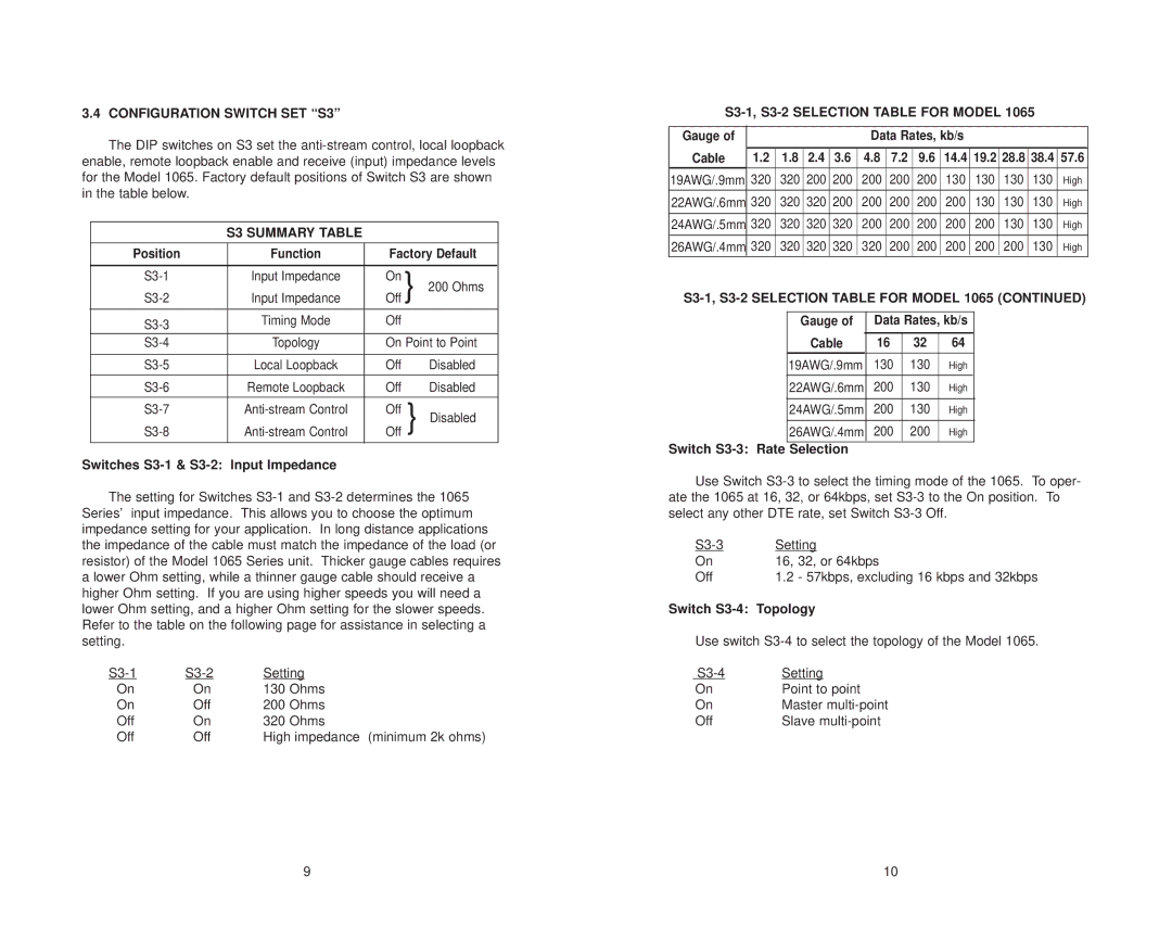
3.4 CONFIGURATION SWITCH SET “S3”
The DIP switches on S3 set the
S3 SUMMARY TABLE
Position | Function | Factory Default | |
|
|
|
|
Input Impedance | On | } 200 Ohms | |
Input Impedance | Off | ||
|
|
|
|
Timing Mode | Off |
| |
|
|
| |
Topology | On Point to Point | ||
|
|
|
|
Local Loopback | Off | Disabled | |
|
|
|
|
Remote Loopback | Off | Disabled | |
|
|
|
|
Off | } Disabled | ||
Off | |||
|
|
|
|
Switches S3-1 & S3-2: Input Impedance
The setting for Switches
Setting | ||
On | On | 130 Ohms |
On | Off | 200 Ohms |
Off | On | 320 Ohms |
Off | Off | High impedance (minimum 2k ohms) |
S3-1, S3-2 SELECTION TABLE FOR MODEL 1065
Gauge of |
|
|
|
| Data Rates, kb/s |
|
|
|
| |||
|
|
|
|
|
|
|
|
|
|
|
|
|
Cable | 1.2 | 1.8 | 2.4 | 3.6 | 4.8 | 7.2 | 9.6 | 14.4 | 19.2 | 28.8 | 38.4 | 57.6 |
19AWG/.9mm | 320 | 320 | 200 | 200 | 200 | 200 | 200 | 130 | 130 | 130 | 130 | High |
|
|
|
|
|
|
|
|
|
|
|
|
|
22AWG/.6mm | 320 | 320 | 320 | 200 | 200 | 200 | 200 | 200 | 130 | 130 | 130 | High |
|
|
|
|
|
|
|
|
|
|
|
|
|
24AWG/.5mm | 320 | 320 | 320 | 320 | 200 | 200 | 200 | 200 | 200 | 130 | 130 | High |
|
|
|
|
|
|
|
|
|
|
|
|
|
26AWG/.4mm | 320 | 320 | 320 | 320 | 320 | 200 | 200 | 200 | 200 | 200 | 130 | High |
Gauge of | Data Rates, kb/s | |||
|
|
|
|
|
Cable | 16 | 32 | 64 | |
|
|
|
|
|
19AWG/.9mm | 130 | 130 | High | |
|
|
|
|
|
22AWG/.6mm | 200 | 130 | High | |
|
|
|
| |
24AWG/.5mm | 200 | 130 | High | |
|
|
|
|
|
26AWG/.4mm | 200 | 200 | High | |
Switch S3-3: Rate Selection
Use Switch
Setting | |
On | 16, 32, or 64kbps |
Off | 1.2 - 57kbps, excluding 16 kbps and 32kbps |
Switch S3-4: Topology
Use switch
Setting | |
On | Point to point |
On | Master |
Off | Slave |
9 | 10 |