DE specifications
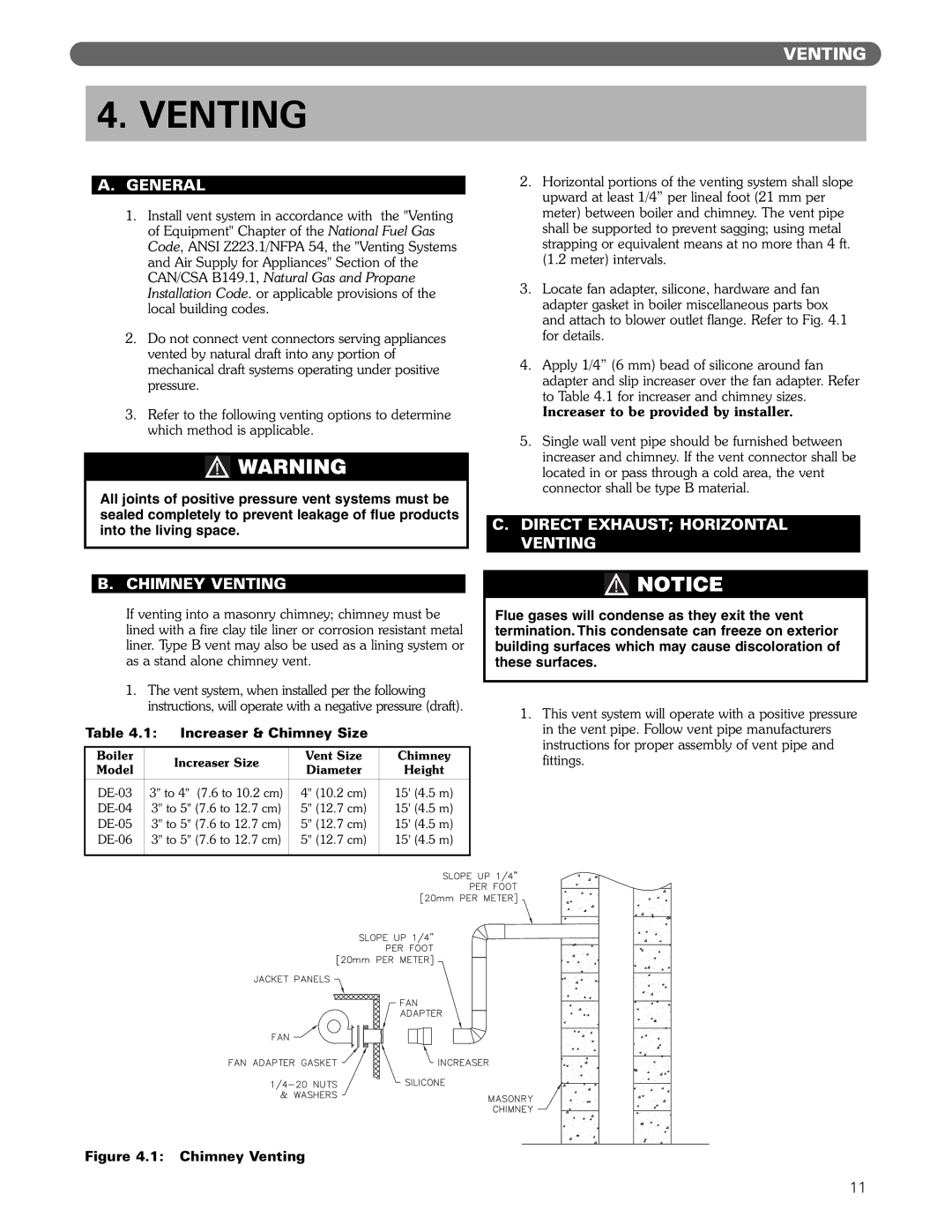
PB Heat DE, recognized for its exceptional heating appliances, is a leading manufacturer of high-efficiency boilers and hydronic heating systems. With a commitment to quality and innovation, PB Heat DE has established itself as a trusted name in the home heating industry. The company emphasizes energy efficiency, reliability, and user comfort, ensuring that their products meet the diverse needs of residential and commercial customers alike.One of the main features of PB Heat DE's products is their robust construction, designed to withstand the demands of daily use while providing consistent and reliable heating. Utilizing advanced materials, such as high-grade steel, these boilers are built to last, reducing the need for frequent repairs or replacements. The durability of PB Heat DE systems translates into significant cost savings over time, making them a smart choice for homeowners looking to invest in their heating solutions.
Incorporating cutting-edge technologies, PB Heat DE offers products equipped with smart controls that allow users to manage their heating systems remotely. This feature provides the ability to adjust temperatures, monitor energy usage, and receive maintenance alerts, all through a smartphone app or web interface. Furthermore, many models are compatible with home automation systems, increasing convenience and efficiency.
Efficiency is a hallmark of PB Heat DE products, with many models boasting high AFUE (Annual Fuel Utilization Efficiency) ratings. This means that they convert a large portion of their fuel into usable heat, reducing energy consumption and lowering utility bills. Additionally, the company's focus on environmentally friendly solutions means that many systems can utilize renewable energy sources, further promoting sustainability.
PB Heat DE also prioritizes user safety, incorporating multiple safety features into their designs. These include automatic shut-off valves, pressure relief valves, and integrated safety sensors that provide homeowners with peace of mind. With these features, PB Heat DE ensures that users can enjoy warmth and comfort without compromising safety.
In summary, PB Heat DE stands out in the heating industry for its dedication to quality, efficiency, and innovation. With durable construction, advanced technologies, high efficiency ratings, and a strong emphasis on user safety, PB Heat DE continues to provide heating solutions that meet the evolving needs of its customers, making it a preferred choice for both residential and commercial applications.

