Installation
PACKAGE CONTENTS
The following items are supplied:
1FT82011 or FR82011 module
1Regulated switching power supply with four plug adapters (North American, Australian, U.K., and European configurations);
1Wall clip with two
1FT82011/FR82011 Fiber Transmitter and Receiver Installation manual (this manual)
SETTING
NOTE: As a matter of convenience, it is recommended that you verify the modes of operation for the
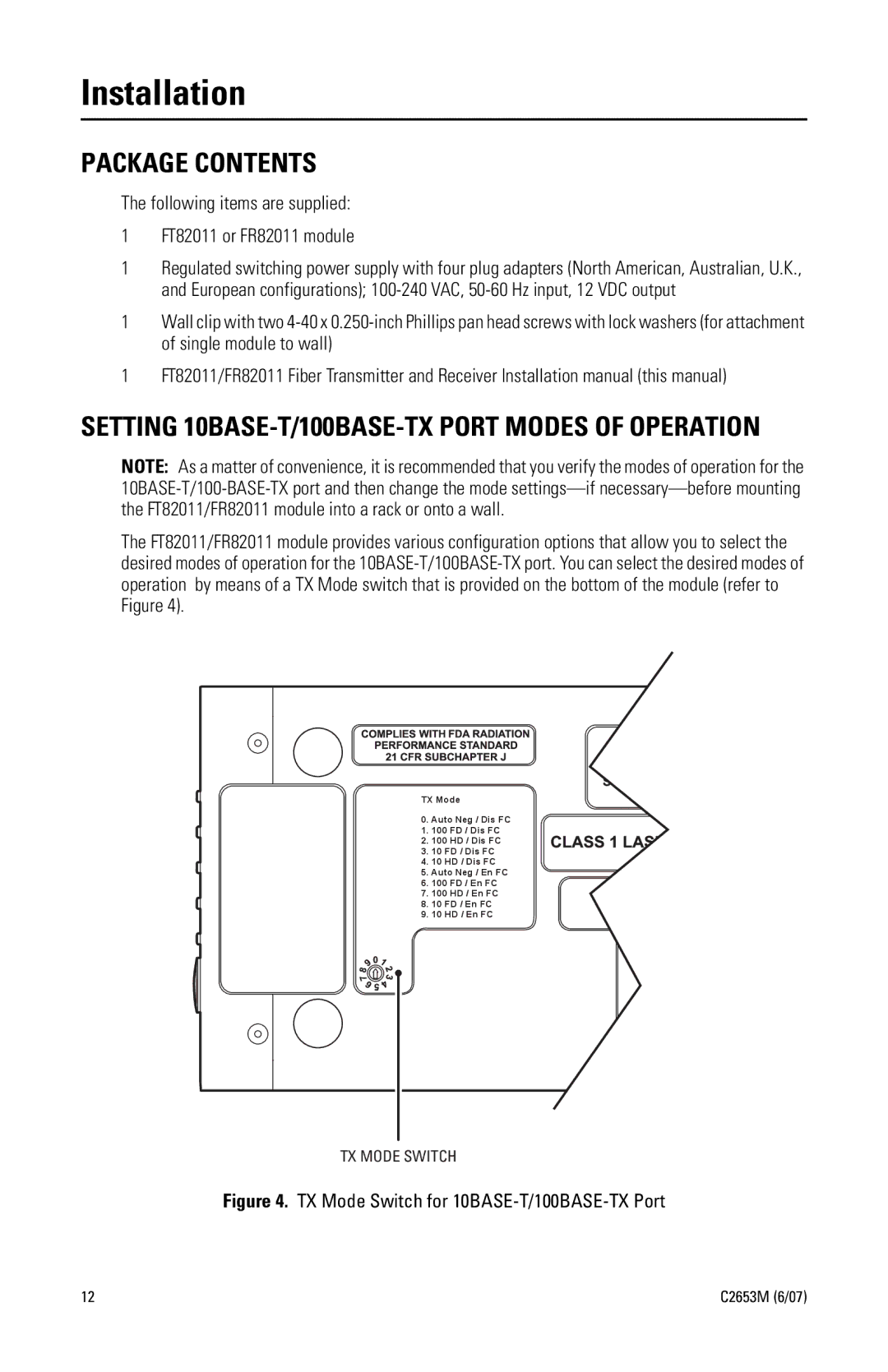
The FT82011/FR82011 module provides various configuration options that allow you to select the desired modes of operation for the
TX Mode
0.Auto Neg / Dis FC
1.100 FD / Dis FC
2.100 HD / Dis FC
3.10 FD / Dis FC
4.10 HD / Dis FC
5.Auto Neg / En FC
6.100 FD / En FC
7.100 HD / En FC
8.10 FD / En FC
9.10 HD / En FC
TX MODE SWITCH
Figure 4. TX Mode Switch for 10BASE-T/100BASE-TX Port
12 | C2653M (6/07) |