Pelco FR82011 manual Rear Panel

Models: FR82011

1 32
Download 32 pages 59 Kb
Page 11
Image 11
REAR PANEL

REAR PANEL

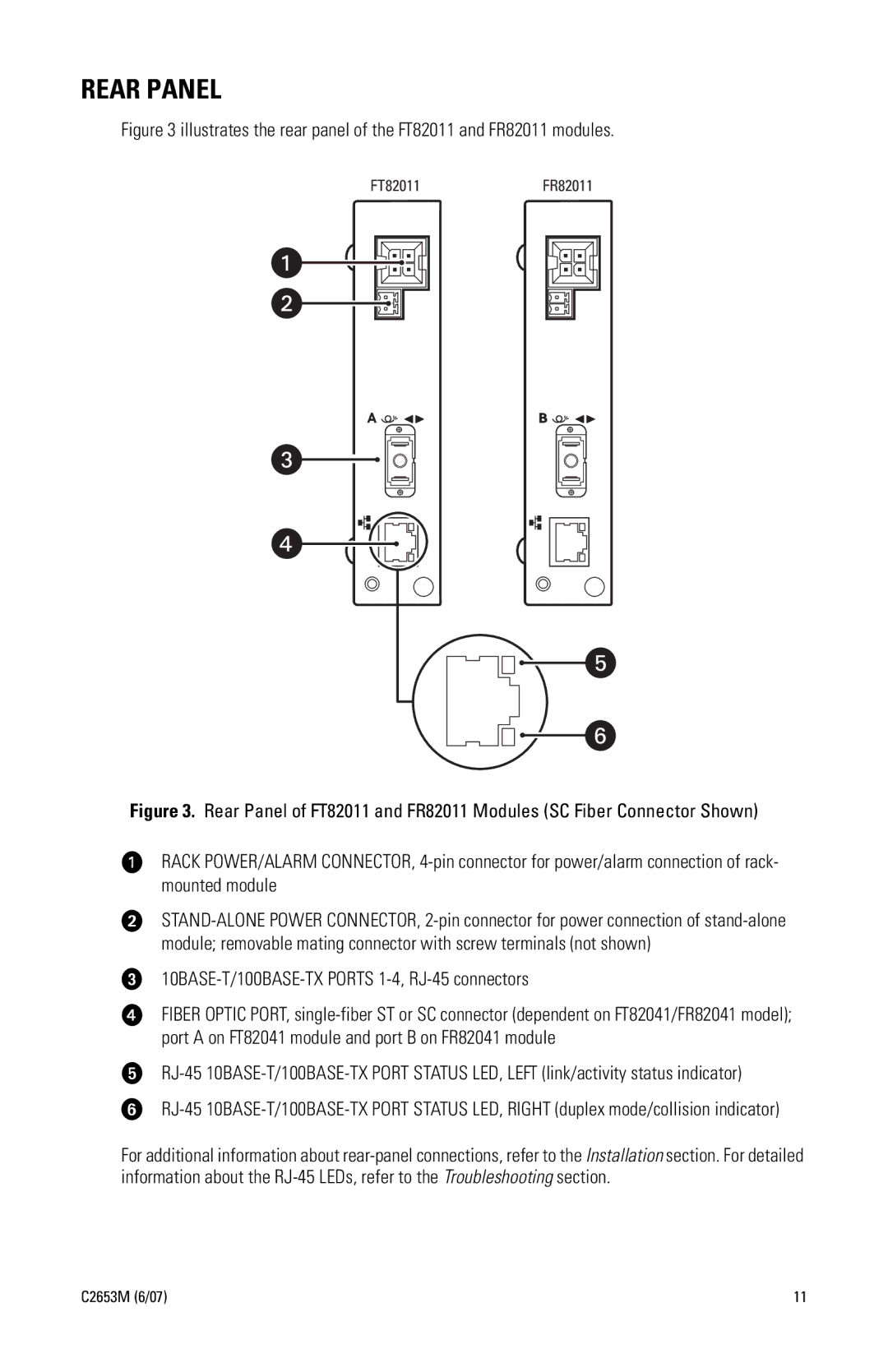
Figure 3 illustrates the rear panel of the FT82011 and FR82011 modules.

FT82011

FR82011

Figure 3. Rear Panel of FT82011 and FR82011 Modules (SC Fiber Connector Shown)

ìRACK POWER/ALARM CONNECTOR, 4-pin connector for power/alarm connection of rack- mounted module

îSTAND-ALONE POWER CONNECTOR, 2-pin connector for power connection of stand-alone module; removable mating connector with screw terminals (not shown)

ï10BASE-T/100BASE-TX PORTS 1-4, RJ-45 connectors

ñFIBER OPTIC PORT, single-fiber ST or SC connector (dependent on FT82041/FR82041 model); port A on FT82041 module and port B on FR82041 module

óRJ-45 10BASE-T/100BASE-TX PORT STATUS LED, LEFT (link/activity status indicator)

rRJ-45 10BASE-T/100BASE-TX PORT STATUS LED, RIGHT (duplex mode/collision indicator)

For additional information about rear-panel connections, refer to the Installation section. For detailed information about the RJ-45 LEDs, refer to the Troubleshooting section.

C2653M (6/07)

11

Page 11
Image 11
Pelco FR82011 manual Rear Panel