I N S T A L L A T I O N
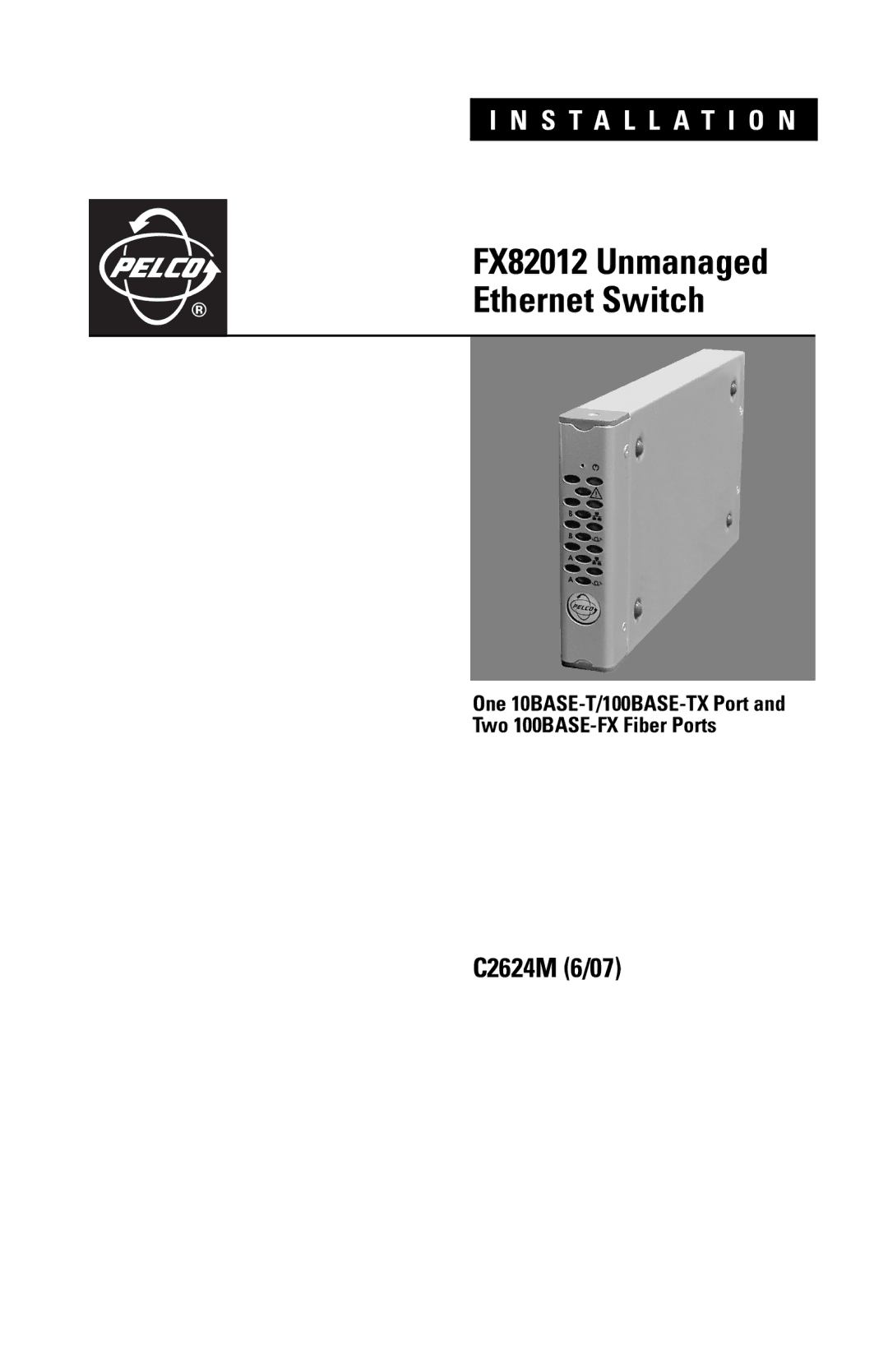
FX82012 Unmanaged
®
One 10BASE-T/100BASE-TX Port and
Two 100BASE-FX Fiber Ports
C2624M (6/07)