G R A D E & H U R R I C A N E S H I E L D D O O R S • P E R F O R M A N C E U P G R A D E
5INSTALL THE PERFORMANCE UPGRADE OR HURRICANESHIELD FASTENERS
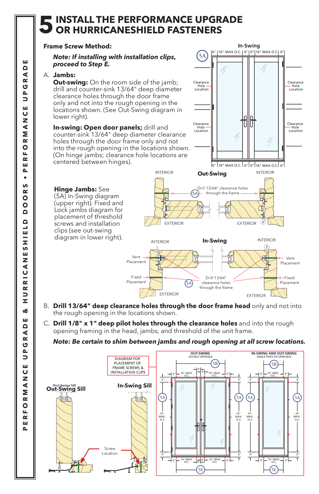
Frame Screw Method: |
Note: If installing with installation clips, | 5A | 6" | 16" MAX O.C. | 6" | 6" 16" MAX O.C. 6" | |
proceed to Step E. |
|
|
|
|
|
|
A. Jambs: |
|
|
|
|
|
|
Clearance |
|
| Clearance | |||
drill and | Hole |
|
|
| Hole | |
Location |
|
| Location | |||
clearance holes through the door frame |
|
|
|
|
| |
only and not into the rough opening in the |
|
|
|
|
| |
locations shown. (See |
|
|
|
|
| |
lower right). |
|
|
|
|
|
|
| Clearance |
|
| Clearance | ||
Hole |
|
|
| Hole | ||
Location |
|
| Location | |||
|
|
|
|
| ||
holes through the door frame only and not |
|
|
|
|
| |
into the rough opening in the locations shown. |
|
|
|
|
| |
(On hinge jambs; clearance hole locations are |
|
|
|
|
| |
centered between hinges). |
|
| 6" | 16" MAX O.C. | 6" | 6" 16" MAX O.C. 6" |
|
|
| ||||
| INTERIOR |
| INTERIOR | |||
Hinge Jambs: See |
| Drill 13/64" clearance holes |
| |||
|
|
| ||||
(5A) |
| 5A | through the frame |
|
| |
|
|
|
|
|
| |
(upper right). Fixed and |
|
|
|
|
|
|
Lock jambs diagram for |
|
|
|
|
|
|
placement of threshold |
|
|
|
|
|
|
screws and installation | EXTERIOR |
|
| EXTERIOR | ||
clips (see |
|
|
|
|
|
|
diagram in lower right). | INTERIOR |
|
| INTERIOR | ||
|
| |||||
Vent | Vent | |
Placement | ||
Placement | ||
|
Fixed |
| Drill 13/64" | Fixed |
Placement | 5A | clearance holes | Placement |
|
| through the frame |
|
| EXTERIOR |
| EXTERIOR |
|
|
|
B.Drill 13/64" deep clearance holes through the door frame head only and not into the rough opening in the locations shown.
C.Drill 1/8" x 1" deep pilot holes through the clearance holes and into the rough opening framing in the head, jambs, and threshold of the unit frame.
Note: Be certain to shim between jambs and rough opening at all screw locations.
P E R F O R M A N C E U P
DIAGRAM FOR
PLACEMENT OF
FRAME SCREWS &
INSTALLATION CLIPS
| |||
|
|
Screw
Location
|
|
| ||||||
| DOUBLE OPERABLE |
|
| SINGLE FIXED OR OPERABLE | ||||
|
|
| 5B |
|
|
| 5B |
|
|
| 6" |
|
|
|
|
|
|
6" | 16" MAX | 6" | 16" MAX | 6" |
| 6" | 16" MAX | 6" |
O.C. |
| O.C. |
| O.C. | ||||
|
|
|
|
|
| |||
6" |
|
|
|
| 6" | 6" |
| 6" |
5A |
|
|
|
| 5A | 5A |
| 5A |
16" |
|
|
|
| 16" | 16" |
| 16" |
MAX. |
|
|
|
| MAX. | MAX. |
| MAX. |
O.C. |
|
|
|
| O.C. | O.C. |
| O.C. |
6" |
|
|
|
| 6" | 6" |
| 6" |
6" | 16" MAX | 6" | 16" MAX | 6" |
| 6" | 16" MAX | 6" |
| O.C. | 6" | O.C. |
|
|
| O.C. |
|
|
| 5E |
|
|
|
| 5E |
|