Pella 818K0100 installation instructions Frame Screw and Installation Clip Methods

Models: 818K0100

1 16
Download 16 pages 49.53 Kb
Page 11
Image 11
Installation Clip Method:

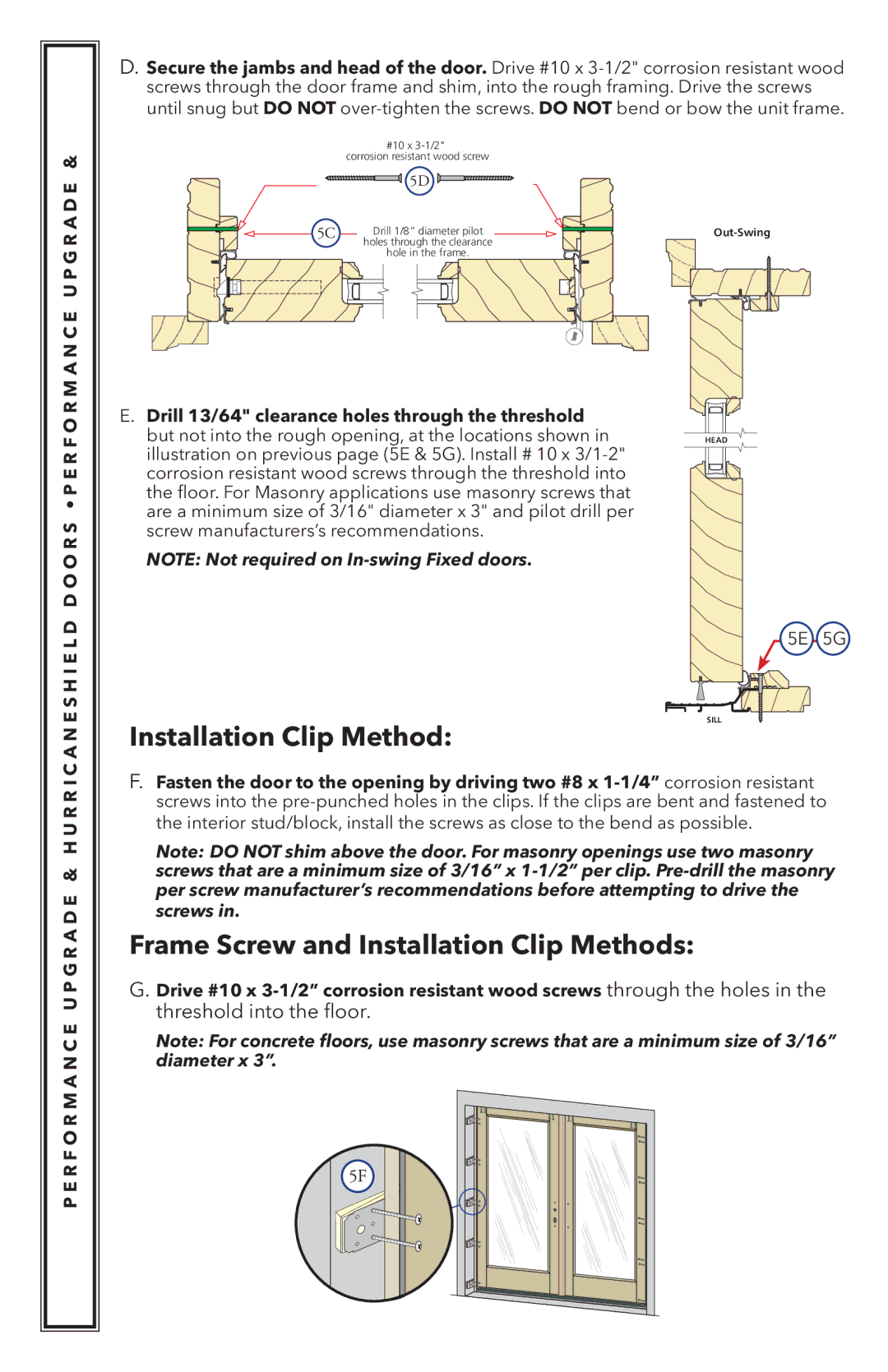
D.Secure the jambs and head of the door. Drive #10 x 3-1/2" corrosion resistant wood screws through the door frame and shim, into the rough framing. Drive the screws until snug but DO NOT over-tighten the screws. DO NOT bend or bow the unit frame.

D D O O R S • P E R FAOP R&M HA UN RC RE I UC AP GN RE AS HD IEE L&D


#10 x 3-1/2"


corrosion resistant wood screw


5D

5C

Drill 1/8” diameter pilot


holes through the clearance

hole in the frame.

E.Drill 13/64" clearance holes through the threshold but not into the rough opening, at the locations shown in illustration on previous page (5E & 5G). Install # 10 x 3/1-2" corrosion resistant wood screws through the threshold into the floor. For Masonry applications use masonry screws that are a minimum size of 3/16" diameter x 3" and pilot drill per screw manufacturers’s recommendations.

NOTE: Not required on In-swing Fixed doors.

Out-Swing

HEAD

P E R F O R M A N C E U P G R A D E & H U R R I C A N E S H I E L

5E 5G

SILL

Installation Clip Method:

F.Fasten the door to the opening by driving two #8 x 1-1/4” corrosion resistant screws into the pre-punched holes in the clips. If the clips are bent and fastened to the interior stud/block, install the screws as close to the bend as possible.

Note: DO NOT shim above the door. For masonry openings use two masonry screws that are a minimum size of 3/16” x 1-1/2” per clip. Pre-drill the masonry per screw manufacturer’s recommendations before attempting to drive the screws in.

Frame Screw and Installation Clip Methods:

G.Drive #10 x 3-1/2” corrosion resistant wood screws through the holes in the threshold into the floor.

Note: For concrete floors, use masonry screws that are a minimum size of 3/16” diameter x 3”.

5F

Page 11
Image 11
Pella 818K0100 installation instructions Frame Screw and Installation Clip Methods