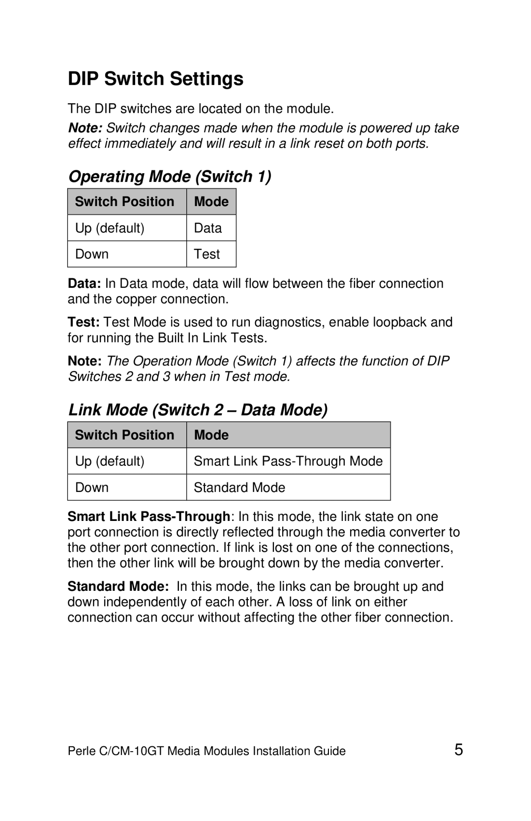
DIP Switch Settings
The DIP switches are located on the module.
Note: Switch changes made when the module is powered up take effect immediately and will result in a link reset on both ports.
Operating Mode (Switch 1)
Switch Position | Mode |
|
|
Up (default) | Data |
|
|
Down | Test |
|
|
Data: In Data mode, data will flow between the fiber connection and the copper connection.
Test: Test Mode is used to run diagnostics, enable loopback and for running the Built In Link Tests.
Note: The Operation Mode (Switch 1) affects the function of DIP Switches 2 and 3 when in Test mode.
Link Mode (Switch 2 – Data Mode)
Switch Position | Mode |
|
|
Up (default) | Smart Link |
|
|
Down | Standard Mode |
|
|
Smart Link
Standard Mode: In this mode, the links can be brought up and down independently of each other. A loss of link on either connection can occur without affecting the other fiber connection.
Perle | 5 |
