240PW9EB/27, 240PW9EB/75, 240PW9EB/69, 240PW9EB/00, 240PW9ES /00 specifications
The Philips 240PW9 series comprises a range of versatile monitors, including models such as the 240PW9ES/00, 240PW9EB/00, 240PW9EB/69, 240PW9EB/75, and 240PW9EB/27. These displays cater primarily to professionals seeking a balance between performance, ergonomics, and visual quality, making them suitable for both office environments and creative workspaces.One of the standout features of the 240PW9 series is its high-resolution display, typically offering a 1920 x 1200 resolution. This extra vertical screen space is particularly advantageous for multitasking, allowing users to view documents side by side or keep multiple applications open simultaneously without sacrificing clarity.
The monitors also employ advanced LCD technology, providing vivid color reproduction and sharp image quality. With an impressive contrast ratio, these monitors deliver deep blacks and bright whites, enhancing the overall viewing experience. The IPS (In-Plane Switching) panel used in these models ensures wide viewing angles, making it easier for multiple users to view the screen without color distortion.
Another key characteristic of the Philips 240PW9 models is their ergonomic design. Many of the monitors in this series come equipped with height-adjustable stands, allowing users to customize the monitor's position for optimal comfort. Additionally, features such as tilt and swivel capabilities enhance the viewing experience, promoting better posture during long hours of work.
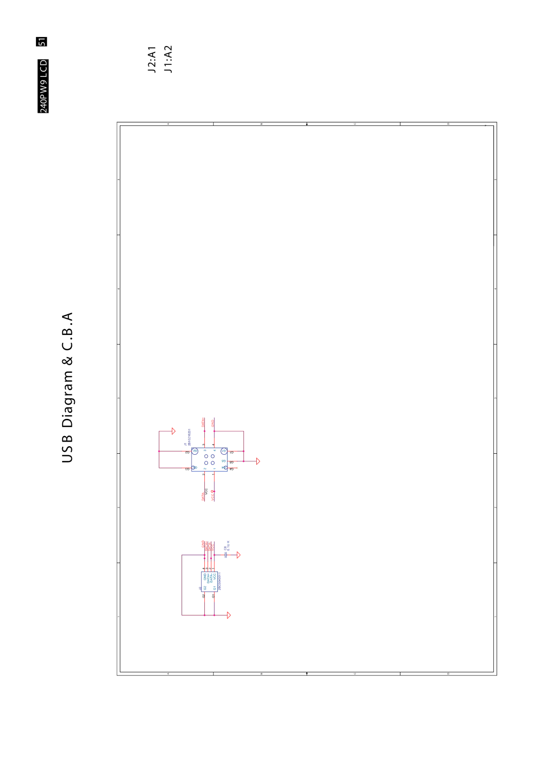
Connectivity options are ample across the Philips 240PW9 series. Users can expect to find multiple inputs, including VGA, DVI, and DisplayPort, facilitating easy connections to various devices such as computers, laptops, and even projectors. This flexibility ensures that users can easily integrate the monitors into their existing setup without requiring additional adapters.
Philips prioritizes eye comfort by incorporating Flicker-Free technology, which reduces eye strain during extended use. Blue Light Filter options further protect users by diminishing the amount of harmful blue light emitted from the screen, contributing to a healthier working environment.
In summary, the Philips 240PW9ES/00, 240PW9EB/00, 240PW9EB/69, 240PW9EB/75, and 240PW9EB/27 models encapsulate a well-rounded package of exceptional display quality, ergonomic features, and versatile connectivity options, making them an excellent choice for professionals seeking reliable and high-quality performance in their workspaces. These monitors reflect Philips' commitment to innovation and user-centric design, ultimately helping to enhance productivity without compromising on comfort.