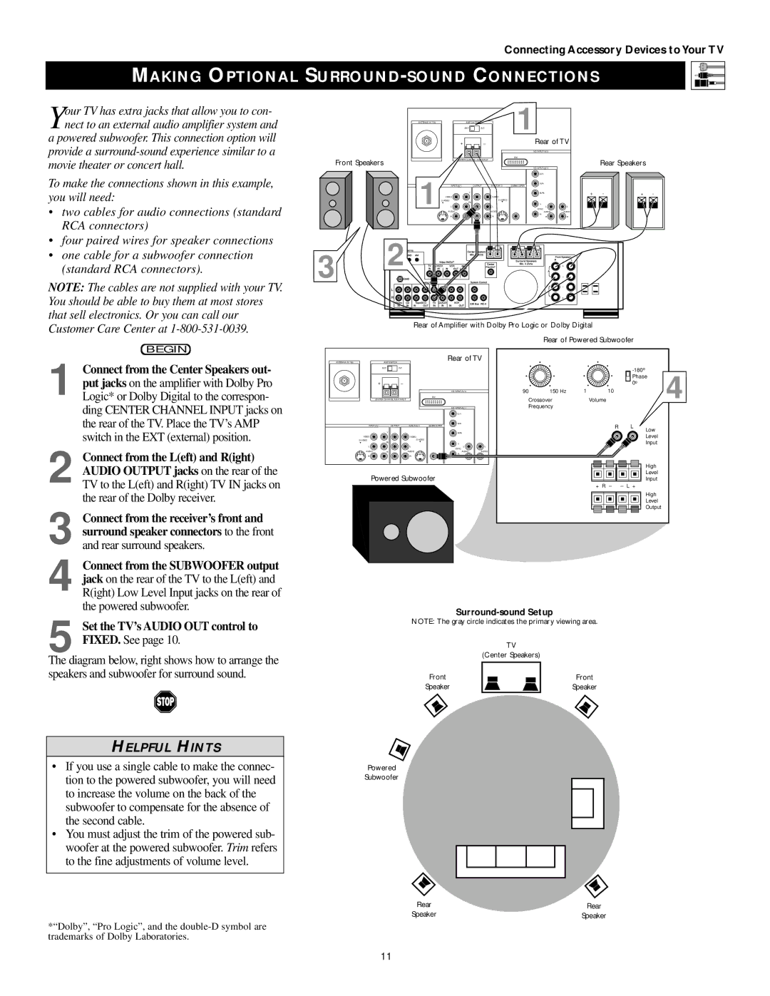
The diagram below, right shows how to arrange the speakers and subwoofer for surround sound.
HELPFUL HINTS
• If you use a single cable to make the connec- tion to the powered subwoofer, you will need to increase the volume on the back of the subwoofer to compensate for the absence of the second cable.
• You must adjust the trim of the powered sub- woofer at the powered subwoofer. Trim refers to the fine adjustments of volume level.
*“Dolby”, “Pro Logic”, and the double-D symbol are trademarks of Dolby Laboratories.
Set the TV’s AUDIO OUT control to FIXED. See page 10.
5
3 Connect from the receiver’s front and surround speaker connectors to the front and rear surround speakers.
4 Connect from the SUBWOOFER output jack on the rear of the TV to the L(eft) and R(ight) Low Level Input jacks on the rear of the powered subwoofer.
Connect from the L(eft) and R(ight) AUDIO OUTPUT jacks on the rear of the TV to the L(eft) and R(ight) TV IN jacks on the rear of the Dolby receiver.
2
Connect from the Center Speakers out- put jacks on the amplifier with Dolby Pro Logic* or Dolby Digital to the correspon- ding CENTER CHANNEL INPUT jacks on the rear of the TV. Place the TV’s AMP switch in the EXT (external) position.
1
Your TV has extra jacks that allow you to con- nect to an external audio amplifier system and
a powered subwoofer. This connection option will provide a surround-sound experience similar to a movie theater or concert hall.
To make the connections shown in this example, you will need:
• two cables for audio connections (standard RCA connectors)
• four paired wires for speaker connections
• one cable for a subwoofer connection (standard RCA connectors).
NOTE: The cables are not supplied with your TV. You should be able to buy them at most stores that sell electronics. Or you can call our Customer Care Center at 1-800-531-0039.
BEGIN
Connecting Accessory Devices to Your TV
MAKING OPTIONAL SURROUND-SOUND CONNECTIONS
ANTENNA IN 75Ω | | AMP SWITCH | 1 | |
| | EXT | INT | | |
| | + | _ | Rear of TV |
| | | | HD INPUT-AV 5 | |
Front Speakers | | | | DVI | |
| CHANNEL AMP INPUT | | |
| | | HD INPUT-AV 4 | |
1 | | | | G/Y | |
| | | R/Pr | |
| INPUT-AV 1 | OUTPUTINPUT-AV 2 | SUBWOOFER | |
| Y | | B/Pb | |
| VIDEO | VIDEO | | |
S-VIDEO | S-VIDEO | | |
L | Pb | L | V | |
| | | |
| L | L | SYNC L | L |
| | AUDIO | AUDIO | AUDIO | AUDIO |
| | | | H | |
| | R | R | R | R |
Rear of Amplifier with Dolby Pro Logic or Dolby Digital
Rear of Powered Subwoofer
ANTENNA IN 75Ω | AMP SWITCH | | Rear of TV |
| EXT | INT | | | |
+ | | _ | | | |
| | | | |
| | | | HD INPUT-AV 5 | |
| | | | DVI | |
CENTER CHANNEL AMP INPUT | | | |
| | | | HD INPUT-AV 4 | |
| | | | G/Y | |
| | | | R/Pr | |
INPUT-AV 1 | | OUTPUT | INPUT-AV 2 | SUBWOOFER | |
| Y | | | B/Pb | |
VIDEO | | | VIDEO | | |
S-VIDEO | | | S-VIDEO | | |
L | Pb | | L | V | |
| | | | |
L | | | L | L | L |
| | | | SYNC | |
AUDIO | Pr | | AUDIO | AUDIO | AUDIO |
| | | | H | |
R | | | R | R | R |
Powered Subwoofer
| | | | -180o | | 4 |
| | | | Phase |
| | | | 0o | |
90 | 150 Hz | 1 | 10 | | |
Crossover | | Volume | | |
Frequency | | | | | |
| | | R | L | Low | |
| | | | | |
| | | | | Level | |
| | | | | Input | |
| High |
| Level |
| Input |
+ R – | – L + |
High
Level
Output
Surround-sound Setup
NOTE: The gray circle indicates the primary viewing area.
TV
(Center Speakers)
Front
Speaker

