Need help fast?
Besoin dune aide Rapide?
Necesita ayuda Inmediata?
Proof of Purchase
For Customer Use
Important Safety Instructions
Safety Information cont’d
Safety Precautions
Declaration of Conformity
Box
Table of Contents
Introduction
Playable Discs and Video Cassettes
Hookups
Determining the best possible connection
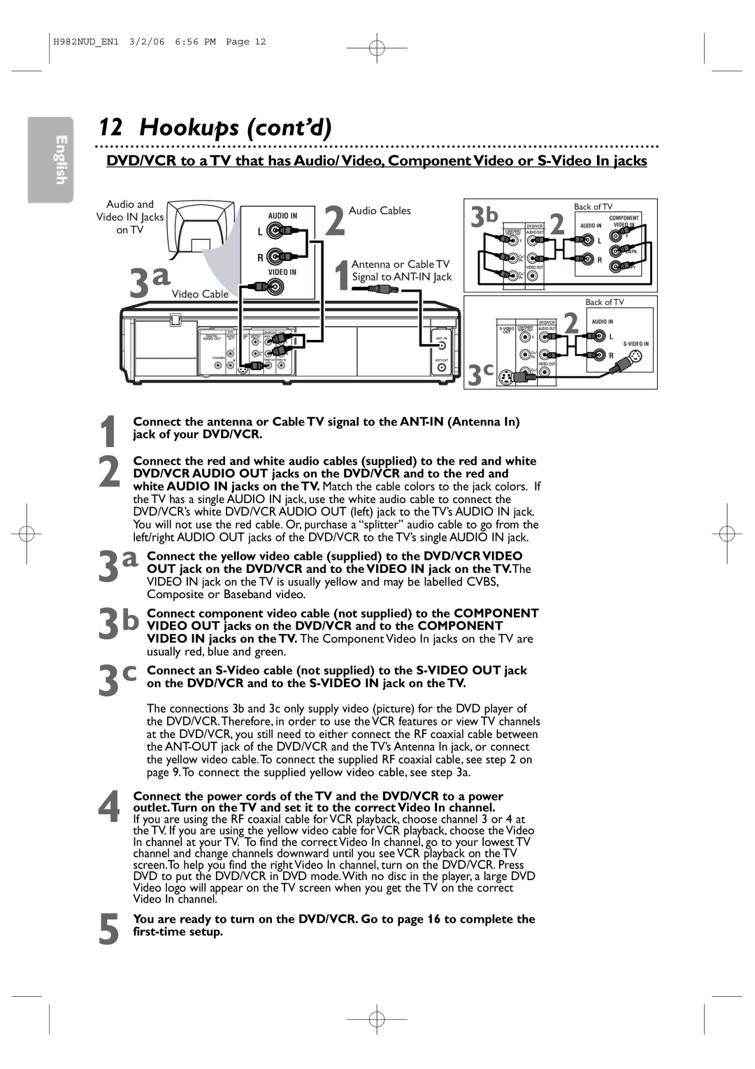
Hookups cont’d
Connections
Remember
Signal
Cable
RF coaxial cable TV’s Antenna
Jack of your DVD/VCR
DVD/VCR Audio OUT jacks on the DVD/VCR and to the red
Composite or Baseband video
Video OUT jacks on the DVD/VCR and to the Component
DVD/VCR to a TV and a Stereo
Check your Stereo manual for details
Stereo
Putting Batteries in the Remote Control
Using the Remote Control
Recycling Guidelines/Battery Safety
First-time DVD/VCR Setup
Other tape playback features are on pages
Video Cassette Playback
Read and follow the steps below to play a tape
Turn on the TV. Insert a tape
Disc Playback
Press OPEN/CLOSE a
On the DVD/VCR
Insert a disc
Display Panel
DVD Display Panel
VCR Display Panel
Display Messages
Front Panel, Rear Panel and Remote Control
Remote Control
Front Panel
Rear Panel
Channel Setup
Adding/Deleting Channels
Press CLEAR/RESET or B to start the clock
Clock VCR
While the DAY space is flashing, press K or L until
While the Year space is flashing, press K or L
Press CLEAR/RESET to remove the menu
Language VCR
VCR Status Displays
Press Display again to remove all the displays
Videotape Recording
Recording Prevention
To stop recording, press Stop C
Turn on the TV Insert a tape in the DVD/VCR
Use the TV remote control to select the channel
Remote control to return to channel 03 or 04 at
Press VCR/TV on the DVD/VCR remote control to
Press VCR, then press Record I to record
When an OTR ends
One-Touch Recording
Stopping an OTR
Point the remote control at DVD/VCR 2. Press
Rerecording Tape Duplication
Make the connections shown above
Turn on the TV and set it to channel 03 or 04
Timer Recording
Timer Recording cont’d
Cancelling Timer Recordings
When a timer recording ends
Press K or L to select a recording tape speed. The arrow
DVD to Videotape Duplication
Speed are on
Repeat Playback
Tape Counter
Time Search, Index Search
Time Search
Index Search
A recording by following these steps
Automatic Operation Features
Special Effects Playback
Multi-Channel Television Sound / Hi-Fi Stereo
Understanding Displays
Multi-Channel Television Sound
Hi-Fi Stereo
Using the Title Menu
Menus, Playback Control PBC Function
Playback Control PBC Function
Press K, L, s or B to select an item, then press OK
During playback, press Search g or h on Remote control
Fast Forward/Reverse Search
Press Play B to return to normal playback
To resume normal playback, press Play B
Title/Chapter Playback,Time Playback
Title/Chapter Playback
Time Playback
Using Search
Track Playback
Pressed within 30 seconds of the previous number
Begin or the current track will continue to play
Paused and Step-by-Step Playback
Resume On
During disc playback, press Pause k. Playback will
Pause and the sound will be mute
Repeat, A-B Repeat
Repeat
Let you start over OFF will appear briefly on
Markers
Within 30 seconds, press s or B to select a Marker
To return to a Marker during playback, press
Subtitles, Camera Angles
Subtitles
Camera Angles
Audio Language, Stereo Sound Mode
Stereo Sound Mode
Audio Language
During DVD playback, press Audio repeatedly to
Slow Motion, Zoom
Slow Motion
Zoom
Press Pause F during DVD or Video CD playback
Program/Random Playback
Program Playback
Random Playback
46 MP3/Windows MediaTM Audio/JPEG Playback
Dual Playback
Folder Playback
Press K or L to select a folder, then press Play B or OK
On-Screen Displays
DVD Displays
Video CD and Audio CD Displays
On-Screen Displays cont’d
Press Display again to remove the display
Black Level,Virtual Surround
Initializing
Black Level
Virtual Surround
Instructions continue on the next
Language cont’d
Instructions from the previous
Language Codes
Select a setting, then press OK
Display
Press s or B to select DISPLAY, then Press OK
Press K or L to select an item, then press OK
You may adjust the Progressive Scan compatibility
Display cont’d
Progressive Scan
If Progressive is ON, this message appears
Audio
While playback is stopped, press
Press s or B to select Custom at the top
Menu, then press OK
Parental Password
Password CHANGE, then press OK
Press DVD to put the DVD/VCR in DVD mode. DVD
While playback is stopped, press SYSTEM/MENU
Parental Levels
Press sor B to select Custom at the top Menu, then press OK
Press sor B to select
PARENTAL, at the top
Others
Press s or B to select OTHERS, then Press OK
If you selected Auto Power OFF, press OK
Repeatedly to choose on or OFF.The default setting is
Others cont’d
ON. Choose on if you want the player to turn off when
Glossary
Cable Box/Satellite Receiver Output Channel 03 or
Helpful Hints
Helpful Hints cont’d
Line Input mode
Cleaning the Video Heads
You cannot insert a video cassette
You cannot remove the tape
Care and Maintenance
Specifications
Limited Warranty
WHO is Covered
Information Index
Controls Dvd/vcr Remote