ADSL | POWER RESET | LAN1 | LAN2 | LAN3 | LAN4 |
1 2 3 4
PWR XDSLOn Line WL | L1 L2 L3 L4 |
InstallationEN
System Requirements
•ADSL line installed by your Internet Service Provider.
•A computer using a fixed IP address or dynamic IP address assigned via DHCP, as well as a gateway server address and DNS server address from your service provider.
•A computer equipped with a 10/100 Mbps network adapter, a
•TCP/IP network protocols installed on each PC that will access the Internet.
•A
Hardware Description
The ADSL Wireless Base Station contains an integrated ADSL modem and connects to the Internet or to a remote site using its
Data passing between devices connected to your local area network can run at up to 100 Mbps over the 10/100 Ethernet ports and 54 Mbps over the
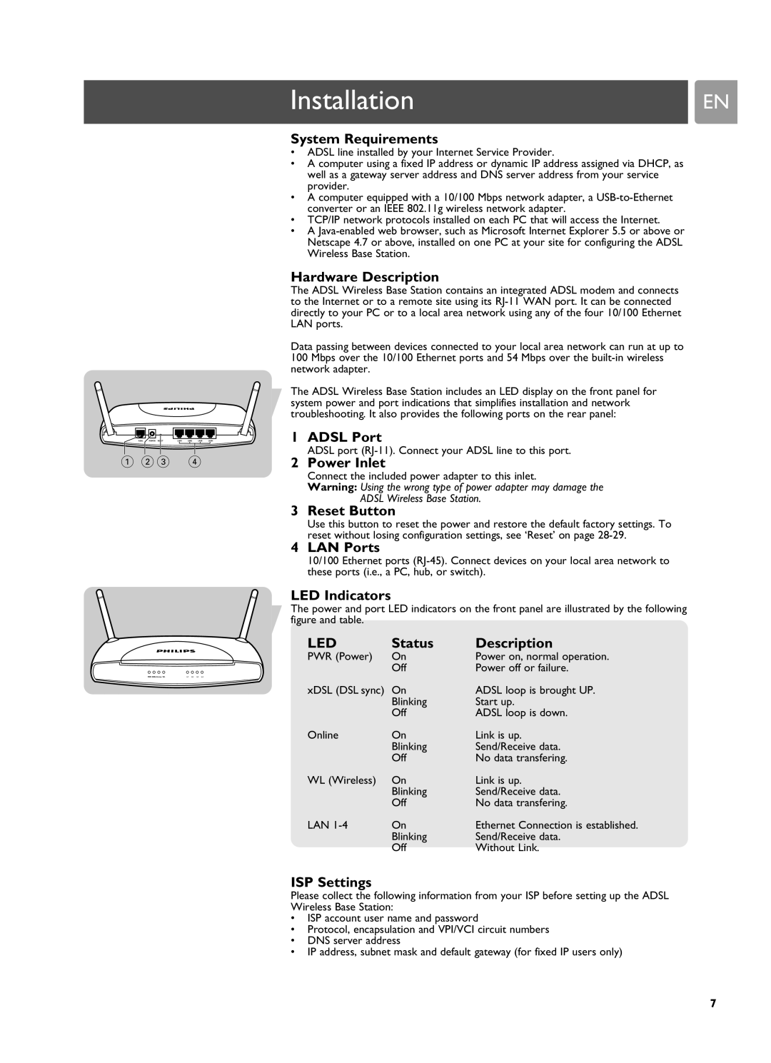
The ADSL Wireless Base Station includes an LED display on the front panel for system power and port indications that simplifies installation and network troubleshooting. It also provides the following ports on the rear panel:
1 ADSL Port
ADSL port (RJ-11). Connect your ADSL line to this port.
2 Power Inlet
Connect the included power adapter to this inlet.
Warning: Using the wrong type of power adapter may damage the
ADSL Wireless Base Station.
3 Reset Button
Use this button to reset the power and restore the default factory settings. To reset without losing configuration settings, see ‘Reset’ on page
4 LAN Ports
10/100 Ethernet ports
LED Indicators
The power and port LED indicators on the front panel are illustrated by the following figure and table.
LED | Status | Description |
PWR (Power) | On | Power on, normal operation. |
| Off | Power off or failure. |
xDSL (DSL sync) | On | ADSL loop is brought UP. |
| Blinking | Start up. |
| Off | ADSL loop is down. |
Online | On | Link is up. |
| Blinking | Send/Receive data. |
| Off | No data transfering. |
WL (Wireless) | On | Link is up. |
| Blinking | Send/Receive data. |
| Off | No data transfering. |
LAN | On | Ethernet Connection is established. |
| Blinking | Send/Receive data. |
| Off | Without Link. |
ISP Settings
Please collect the following information from your ISP before setting up the ADSL Wireless Base Station:
•ISP account user name and password
•Protocol, encapsulation and VPI/VCI circuit numbers
•DNS server address
•IP address, subnet mask and default gateway (for fixed IP users only)
7