
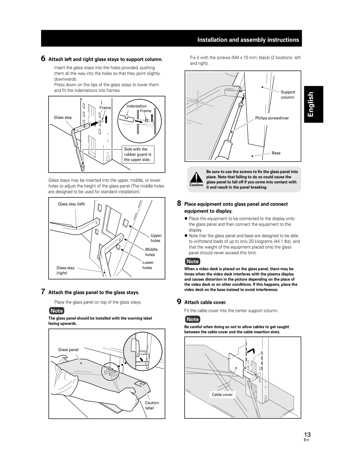
PDK-FS05 specifications
The Pioneer PDK-FS05 is a cutting-edge digital audio player designed for audiophiles and music enthusiasts seeking high-fidelity sound reproduction and modern connectivity features. This device stands out in a crowded market due to its versatility and technological advancements that appeal to users across different genres and use cases.One of the defining characteristics of the PDK-FS05 is its exceptional sound quality. It is equipped with high-resolution audio capabilities, supporting formats up to 32-bit/384 kHz, which ensures that music is played back with impeccable detail and clarity. The built-in DAC (Digital-to-Analog Converter) is engineered to minimize distortion and enhance the dynamic range, allowing users to experience music as it was intended by the artists.
The PDK-FS05 supports a range of audio formats, including lossless options like FLAC and WAV, which cater to the demands of the most discerning listeners. This versatility is crucial for ensuring that all types of audio files can be played without compromising sound quality.
Connectivity is another strong suit of the PDK-FS05. It features Bluetooth capabilities, allowing users to stream music wirelessly from their smartphones or tablets. Additionally, the player is equipped with Wi-Fi functionality, enabling access to various streaming services, including popular platforms like Spotify and Tidal. This ensures that users have a vast library of music at their fingertips, making it easier to enjoy their favorite tracks without the need for local storage.
The PDK-FS05 also includes a user-friendly touchscreen interface, which simplifies navigation through playlists and settings. The intuitive layout allows for quick access to essential features, making for a seamless user experience. This modern design is complemented by a sleek and compact form factor, ensuring that the device is both portable and aesthetically pleasing.
Battery life is another significant aspect of the PDK-FS05. With long-lasting power, users can enjoy hours of uninterrupted listening, whether at home or on the go. This convenience is essential for those who value mobility and wish to carry their music with them.
In conclusion, the Pioneer PDK-FS05 is a remarkable digital audio player that combines high-resolution audio capabilities, extensive format support, versatile connectivity options, and user-friendly design. It is a fantastic choice for anyone looking to elevate their listening experience and fully appreciate the nuances of their favorite music.