Installation and Connections
English
Installation and Connections
Connection to INPUT1 and INPUT2
The INPUT 1 and INPUT 2 jacks are used to connect the display to a computer. After making the connections, adjust the screen settings in accordance with the computer’s signal output. See pages
| INPUT2 | [ON SYNC] |
|
| [H/V SYNC] |
|
Output | jack | G | B | R | HD | VD |
|
|
|
|
|
| |
source |
|
|
|
|
|
|
Personal |
|
|
|
|
|
|
computer (PC) | G ON SYNC | B | R |
|
| |
with RGB output |
|
| ||||
|
| G | B | R | H/V SYNC |
|
|
| G | B | R | HD | VD |
 : Do not connect anything.
  : Connect to this jack.
Note
Components compatible with INPUT1 are also compatible with INPUT2.
INPUT1 is compatible with Microsoft’s Plug & Play (VESA DDC 1/2B).
When making connections to INPUT1, please refer to supplement 2 on page 37.
For the screen sizes and input signals that INPUT1 and INPUT2 are compatible with, please refer to supplement 1 (pages 35 and 36).
Connection to a personal computer
Connection method differs depending on the computer type. When connecting, please thoroughly read the computer’s instruction manual.
Before making connections, be sure to make sure that the personal computer’s power and this unit’s main power is off.
For the PC input signals and screen sizes that this unit is compatible with, please refer to supplement 1 (pages 35 and 36).
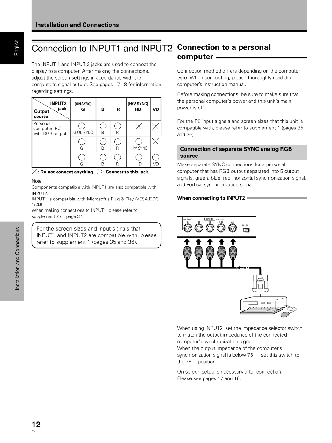
Connection of separate SYNC analog RGB
source
Make separate SYNC connections for a personal computer that has RGB output separated into 5 output signals: green, blue, red, horizontal synchronization signal, and vertical synchronization signal.
When connecting to INPUT2
(ON SYNC) |
| INPUT2 | (H/V SYNC) |
|
G | B | R | HD | VD |
75Ω Ô2k.Ω2
When using INPUT2, set the impedance selector switch to match the output impedance of the connected computer’s synchronization signal.
When the output impedance of the computer’s synchronization signal is below 75 Ω , set this switch to the 75 Ω position.
Please see pages 17 and 18.
12
En