where
When terminated with a
Displayed image intensity and colors will change linearly with the video analog input. This is necessary to provide a uniform user color change on the screen in response to a uniformly stepped analog input. The Monitor must be capable of resolving a minimum color range of 262,144 displayable colors (6 bit resolution for Red, Green and Blue). This interpolates to 64 shades of gray (or color) at the Red, Green, and Blue analog video inputs. Accomplishing specified shades of gray requires a “Video Gain” control adjustment (Section 15.0 ) of Red, Green, and Blue analog input signals based on the maximum output level range previously specified.
| OVERSHOOT | HIGH |
POS |
| STEADY |
|
| LEVEL |
|
| LOW |
NEG |
| STEADY |
|
| LEVEL |
RISE | FALL |
|
TIME | TIME |
|
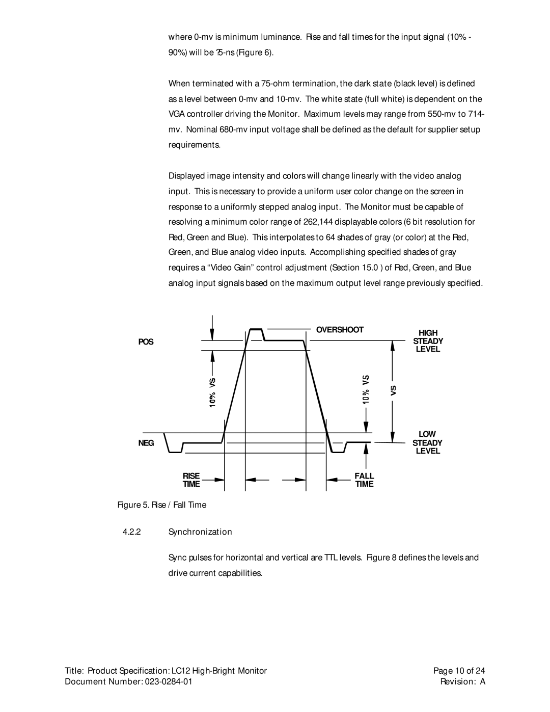
Figure 5. Rise / Fall Time
4.2.2Synchronization
Sync pulses for horizontal and vertical are TTL levels. Figure 8 defines the levels and drive current capabilities.
Title: Product Specification: LC12 | Page 10 of 24 |
Document Number: | Revision: A |