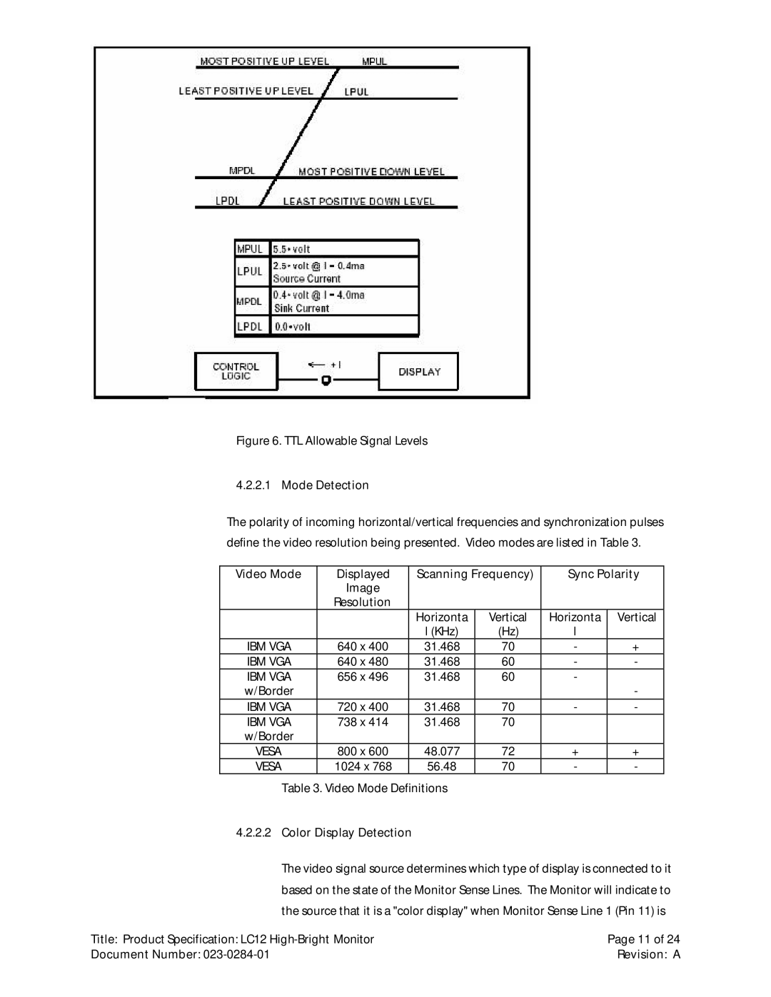
Figure 6. TTL Allowable Signal Levels
4.2.2.1 Mode Detection
The polarity of incoming horizontal/vertical frequencies and synchronization pulses define the video resolution being presented. Video modes are listed in Table 3.
Video Mode | Displayed | Scanning Frequency) | Sync Polarity | ||
| Image |
|
|
|
|
| Resolution |
|
|
|
|
|
| Horizonta | Vertical | Horizonta | Vertical |
|
| l (KHz) | (Hz) | l |
|
IBM VGA | 640 x 400 | 31.468 | 70 | - | + |
IBM VGA | 640 x 480 | 31.468 | 60 | - | - |
IBM VGA | 656 x 496 | 31.468 | 60 | - |
|
w/Border |
|
|
|
| - |
IBM VGA | 720 x 400 | 31.468 | 70 | - | - |
IBM VGA | 738 x 414 | 31.468 | 70 |
|
|
w/Border |
|
|
|
|
|
VESA | 800 x 600 | 48.077 | 72 | + | + |
VESA | 1024 x 768 | 56.48 | 70 | - | - |
Table 3. Video Mode Definitions
4.2.2.2Color Display Detection
The video signal source determines which type of display is connected to it based on the state of the Monitor Sense Lines. The Monitor will indicate to the source that it is a "color display" when Monitor Sense Line 1 (Pin 11) is
Title: Product Specification: LC12 | Page 11 of 24 |
Document Number: | Revision: A |