4.0Video Signal Input Requirements
4.1Video Input Lines
The Video Signal Connector consists of fifteen (15) positions wired numerically and supplied attached to the Monitor as a chassis mounted connector per definitions listed in Table 2. The "NC" positions of this connector are not used for any purpose.
Pin Number | Signal Name |
1 | Red Video |
2 | Green Video |
3 | Blue Video |
4 | Monitor Sense Line 3 |
| (connected to Pin 10) |
5 | NC |
6 | Red video return |
7 | Green video return |
8 | Blue video return |
9 | NC |
10 | Signal Ground Reference |
11 | Monitor Sense Line 1 |
| (connected to Pin 10) |
12 | Monitor Sense Line 2 (NC) |
13 | Horizontal Sync Input |
14 | Vertical Sync Input |
15 | NC |
Table 2. Video Signal Connector – Pin Number Assignments
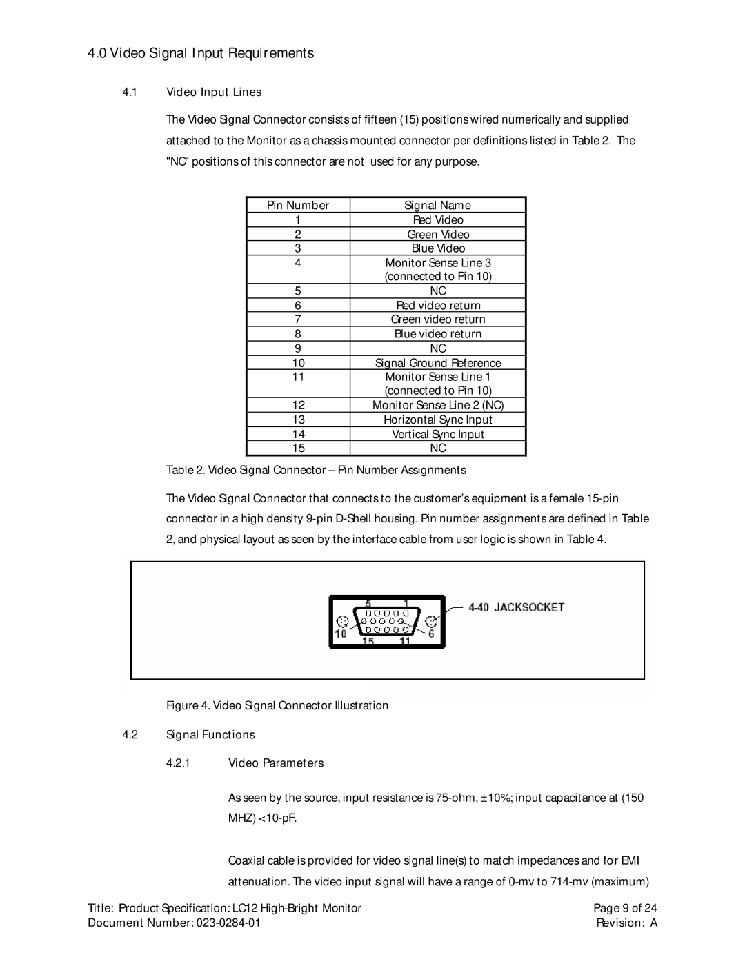
The Video Signal Connector that connects to the customer’s equipment is a female
Figure 4. Video Signal Connector Illustration
4.2Signal Functions
4.2.1Video Parameters
As seen by the source, input resistance is 75-ohm, ±10%; input capacitance at (150 MHZ) <10-pF.
Coaxial cable is provided for video signal line(s) to match impedances and for EMI attenuation. The video input signal will have a range of
Title: Product Specification: LC12 | Page 9 of 24 |
Document Number: | Revision: A |