Brushbulltm
To the Dealer
Introduction
To the Owner
Table of Contents
General Information
Specifications
BB48X BB60X BB72X BB84X
Safety
Free Mower Safety Video
Training Package for Rotary Mowers/Cutters-English/Spanish
Training Package for Rotary Mowers/Cutters-English
Woods Equipment Company
Operation
Safety Rules
Training
Preparation
Maintenance
Storage
Serial Number Plate
Safety & Instructional Decals
RED Rear Reflector
Crushing and Pinching Hazard
Be Careful
Attaching Cutter to Tractor BB48X only
Operation
Operation
Tractor Stability
Quick Hitch Attachment BB48X Only
Top Link Adjustment BB48X Only
Attaching Cutter to Tractor BB60X, BB72X, BB84X only
Installation and Removal Driveline Tractor PTO
Shortening Driveline
Driveline Attachment
Driveline Interference Check
Cutting Height Adjustment
Shredding Material
Operating Technique
Check Chain Adjustment
PRE-OPERATION Check List
Lubrication Information
Owner Service
Owner Service
Blocking Method
Blade Servicing
Blade Installation Figure
Blade Removal Figure
Walterscheid BB84X Only
Slip Clutch Adjustment
Blade Sharpening
Comer
Model
Walterscheid
Cleaning
Driveline Shear Bolt Replacement
Shielding Repair
Problem Possible Cause Solution
Troubleshooting
Mowing Conditions
Seal Replacement
Dealer Service
Dealer Service
Gearbox Maintenance
Gearbox Repair
Seal Repair
Vertical Shaft Seal Repair
Horizontal Seal Leak Repair
Reassemble Gearbox
Reinstall Gearbox
BB48X, BB60X, BB72X
BB72X S/N 1159929 and Above only
On CAST/CROWN TOP BB48X, BB60X
Reassemble Gearbox Cast Top BB48X
Reassemble Gearbox Cast Top BB60X and BB72X
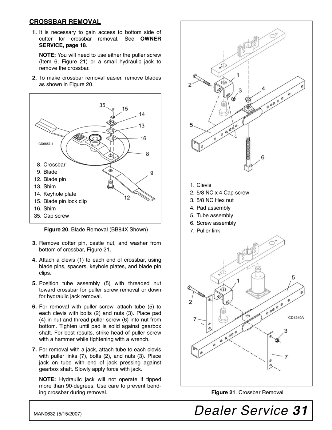
Crossbar Removal
Crossbar Removal
Joint Disassembly
Crossbar Installation
Universal Joint Repair
Install Cups
Joint Assembly
Delivery Check List
Dealer Check Lists
Dealer Check Lists
PRE-DELIVERY Check List
Dealer Check Lists
Assembly
Assembly
Dealer SET-UP Instructions
Disassemble Shipping Unit Figure
BB60X, BB72X & BB84X Shipping Configuration
BB60X, BB72X & BB84X
Install A-FRAME
Install A-FRAME to Diagonal Brace Bars
BB48X
BB48X Quick Hitch Set-Up
Install Tailwheel
Install Dual Tailwheel BB84XD Optional
BB48X Standard Hitch Set-Up
Driveline Slip Clutch Optional on BB48X & BB60X
Install Driveline
BB60X, BB72X & BB84X Standard & Quick Hitch Set-Up
Shear Bolt Driveline BB48X & BB60X Only
Fill Gearbox
Install Safety Shielding
Driveline Slip Clutch BB72X and BB84X
Rubber Deflector Standard
BB60X BB72X
Install Optional Check Chains
BB84X
Parts
Parts Index Brushbulltm
BB48X, BB60X, BB72X & BB84X BB84X Shown
Brushbull STANDARD-DUTY Main Assembly
BB72X, BB84X
BB48X, BB60X, BB72X & BB84X Main Assembly Parts List
Gearbox repair asy BB72X S/N 1159928 and Below
Gearbox Assembly Flat TOP
Check Chain Assembly Optional
Gearbox Assembly Parts List
BB48X
Gearbox Assembly CAST/CROWN TOP
BB48X Comer Standard Driveline Assembly
BB60X Comer Standard Driveline Assembly
BB48X & BB60X Comer Slip Clutch Driveline Assembly Optional
BB72X Comer Slip Clutch Driveline Assembly
Series 50 Series
BB84X Comer Slip Clutch Driveline Assembly
BB84X Walterscheid Slip Clutch Driveline Assembly
Front Rubber Shielding Standard
Front & Rear Chain Shielding Optional
Metric Series
Bolt Torque Chart
SAE Series Torque Chart
Appendix
Abbreviations
Bolt Size Chart
Index
Index
Warranty
Rev /23/2005