3.Install driveline onto gearbox input shaft and secure with bolt (1) and nut (2).
4.Secure driveline with bolt (1) and nut (2).
5.Lubricate rear driveline half and install front driveline half.
6.Attach tether chain to diagonal brace bar.
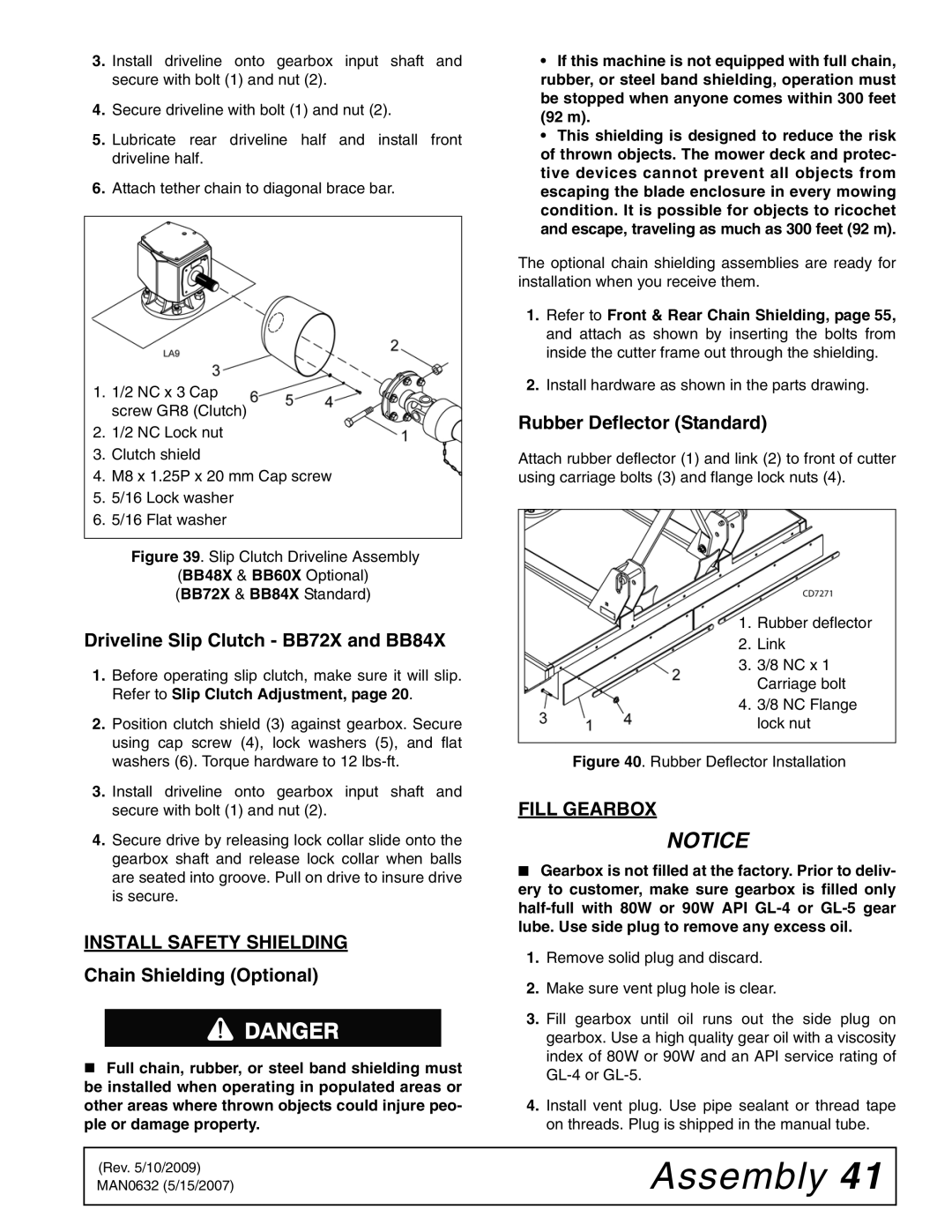
1.1/2 NC x 3 Cap screw GR8 (Clutch)
2.1/2 NC Lock nut
3.Clutch shield
4.M8 x 1.25P x 20 mm Cap screw
5.5/16 Lock washer
6.5/16 Flat washer
Figure 39. Slip Clutch Driveline Assembly
(BB48X & BB60X Optional)
(BB72X & BB84X Standard)
Driveline Slip Clutch - BB72X and BB84X
1.Before operating slip clutch, make sure it will slip. Refer to Slip Clutch Adjustment, page 20.
2.Position clutch shield (3) against gearbox. Secure using cap screw (4), lock washers (5), and flat washers (6). Torque hardware to 12
3.Install driveline onto gearbox input shaft and secure with bolt (1) and nut (2).
4.Secure drive by releasing lock collar slide onto the gearbox shaft and release lock collar when balls are seated into groove. Pull on drive to insure drive is secure.
INSTALL SAFETY SHIELDING
•If this machine is not equipped with full chain, rubber, or steel band shielding, operation must be stopped when anyone comes within 300 feet (92 m).
•This shielding is designed to reduce the risk of thrown objects. The mower deck and protec- tive devices cannot prevent all objects from escaping the blade enclosure in every mowing condition. It is possible for objects to ricochet and escape, traveling as much as 300 feet (92 m).
The optional chain shielding assemblies are ready for installation when you receive them.
1.Refer to Front & Rear Chain Shielding, page 55, and attach as shown by inserting the bolts from inside the cutter frame out through the shielding.
2.Install hardware as shown in the parts drawing.
Rubber Deflector (Standard)
Attach rubber deflector (1) and link (2) to front of cutter using carriage bolts (3) and flange lock nuts (4).
1. Rubber deflector
2. Link
3. 3/8 NC x 1 Carriage bolt
4. 3/8 NC Flange lock nut
Figure 40. Rubber Deflector Installation
FILL GEARBOX
NOTICE
■Gearbox is not filled at the factory. Prior to deliv- ery to customer, make sure gearbox is filled only
1.Remove solid plug and discard.
Chain Shielding (Optional)
Full chain, rubber, or steel band shielding must be installed when operating in populated areas or other areas where thrown objects could injure peo- ple or damage property.
2.Make sure vent plug hole is clear.
3.Fill gearbox until oil runs out the side plug on gearbox. Use a high quality gear oil with a viscosity index of 80W or 90W and an API service rating of
4.Install vent plug. Use pipe sealant or thread tape on threads. Plug is shipped in the manual tube.
(Rev. 5/10/2009) MAN0632 (5/15/2007)