3.Adjust the tractor lower
4.Adjust tractor drawbar so that it will not interfere with cutter or driveline.
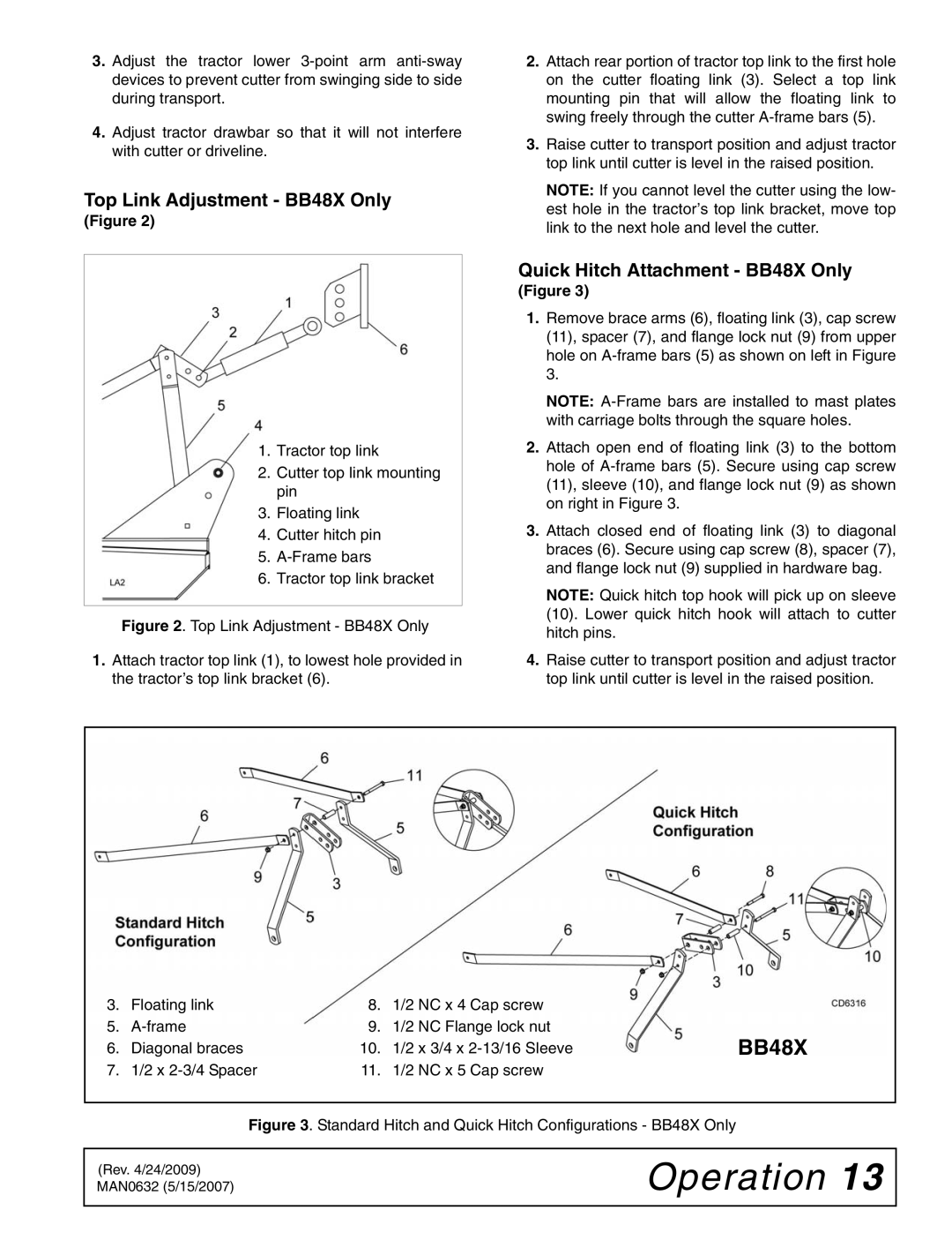
Top Link Adjustment - BB48X Only
(Figure 2)
1.Tractor top link
2.Cutter top link mounting pin
3.Floating link
4.Cutter hitch pin
5.
6.Tractor top link bracket
Figure 2. Top Link Adjustment - BB48X Only
1.Attach tractor top link (1), to lowest hole provided in the tractor’s top link bracket (6).
2.Attach rear portion of tractor top link to the first hole on the cutter floating link (3). Select a top link mounting pin that will allow the floating link to swing freely through the cutter A-frame bars (5).
3.Raise cutter to transport position and adjust tractor top link until cutter is level in the raised position.
NOTE: If you cannot level the cutter using the low- est hole in the tractor’s top link bracket, move top link to the next hole and level the cutter.
Quick Hitch Attachment - BB48X Only
(Figure 3)
1.Remove brace arms (6), floating link (3), cap screw (11), spacer (7), and flange lock nut (9) from upper hole on
NOTE:
2.Attach open end of floating link (3) to the bottom hole of
3.Attach closed end of floating link (3) to diagonal braces (6). Secure using cap screw (8), spacer (7), and flange lock nut (9) supplied in hardware bag.
NOTE: Quick hitch top hook will pick up on sleeve (10). Lower quick hitch hook will attach to cutter hitch pins.
4.Raise cutter to transport position and adjust tractor top link until cutter is level in the raised position.
3. | Floating link | 8. | 1/2 NC x 4 Cap screw |
|
5. | 9. | 1/2 NC Flange lock nut | BB48X | |
6. | Diagonal braces | 10. | 1/2 x 3/4 x | |
7. | 1/2 x | 11. | 1/2 NC x 5 Cap screw |
|
Figure 3. Standard Hitch and Quick Hitch Configurations - BB48X Only
(Rev. 4/24/2009) MAN0632 (5/15/2007)