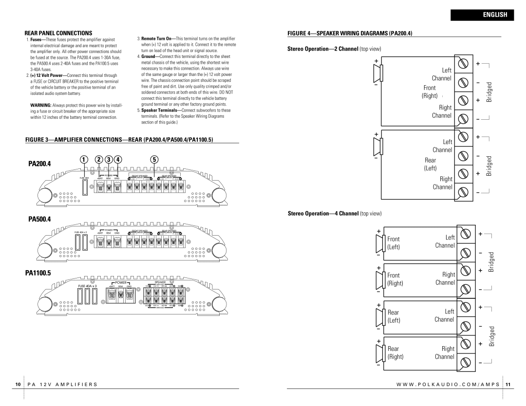
PA200.4 specifications
The Polk Audio PA200.4 is an impressive amplifier designed to deliver powerful and high-quality sound for both novice and expert audio enthusiasts. This 4-channel amplifier is part of Polk's PA series and stands out due to its exceptional features and advanced technologies, making it a popular choice for those wishing to upgrade their car audio systems.One of the main characteristics of the PA200.4 is its robust power output. The amplifier boasts 50 watts RMS per channel at 4 ohms, delivering an impressive 100 watts RMS at 2 ohms. This substantial power allows for loud, clear sound reproduction, perfect for driving high-performance speakers without distortion. The amplifier operates efficiently, providing consistent power even at lower volumes, ensuring that music remains rich and detailed across various listening levels.
The PA200.4 incorporates a range of technologies designed to enhance sound quality and improve user experience. The built-in high and low-pass filters allow for comprehensive tuning, enabling users to optimize the sound for their specific audio setup. The high-pass filter can be adjusted between 80 Hz and 120 Hz, while the low-pass filter also offers flexibility, catering to different types of speakers and subwoofers.
Another key feature of this amplifier is its impressive heat management system. Equipped with an advanced thermal management design, the PA200.4 is engineered to dissipate heat effectively, ensuring prolonged performance even during extended listening sessions. This is essential for maintaining sound quality and preventing damage to the components over time.
The PA200.4's construction is rugged and durable, featuring a compact chassis that makes installation straightforward in various vehicle models. Its lightweight design does not compromise its resilience and quality, making it a practical choice for those who may have limited space in their vehicle.
In summary, the Polk Audio PA200.4 is a versatile and powerful 4-channel amplifier that delivers superior sound quality with flexible tuning options. With its effective power output, advanced technologies, and solid construction, it is a compelling choice for anyone looking to enhance their car audio experience. Whether you are a seasoned audio enthusiast or just starting on your audio journey, the PA200.4 offers the features and performance to meet your needs.

