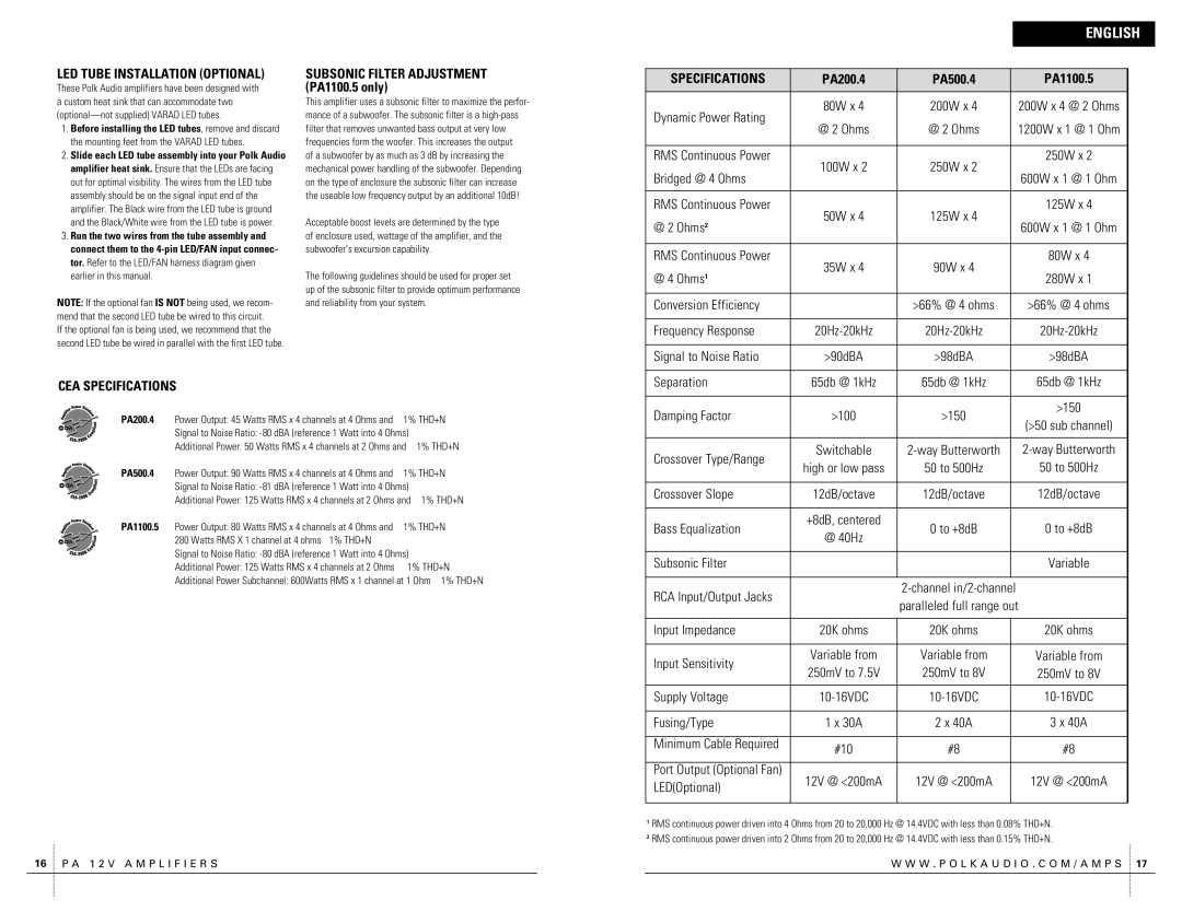
Polk Audio PA200.4 owner manual English, Led Tube Installation Optional, Cea Specifications

Models: PA200.4

1 43
Download 43 pages 14.97 Kb
Page 9
Image 9
LED TUBE INSTALLATION (OPTIONAL)

LED TUBE INSTALLATION (OPTIONAL)

These Polk Audio amplifiers have been designed with a custom heat sink that can accommodate two (optional—not supplied) VARAD LED tubes.

1.Before installing the LED tubes, remove and discard the mounting feet from the VARAD LED tubes.

2.Slide each LED tube assembly into your Polk Audio amplifier heat sink. Ensure that the LEDs are facing out for optimal visibility. The wires from the LED tube assembly should be on the signal input end of the amplifier. The Black wire from the LED tube is ground and the Black/White wire from the LED tube is power.

3.Run the two wires from the tube assembly and connect them to the 4-pin LED/FAN input connec- tor. Refer to the LED/FAN harness diagram given earlier in this manual.

NOTE: If the optional fan IS NOT being used, we recom- mend that the second LED tube be wired to this circuit. If the optional fan is being used, we recommend that the second LED tube be wired in parallel with the first LED tube.

SUBSONIC FILTER ADJUSTMENT (PA1100.5 only)

This amplifier uses a subsonic filter to maximize the perfor- mance of a subwoofer. The subsonic filter is a high-pass filter that removes unwanted bass output at very low frequencies form the woofer. This increases the output

of a subwoofer by as much as 3 dB by increasing the mechanical power handling of the subwoofer. Depending on the type of enclosure the subsonic filter can increase the useable low frequency output by an additional 10dB!

Acceptable boost levels are determined by the type of enclosure used, wattage of the amplifier, and the subwoofer’s excursion capability.

The following guidelines should be used for proper set up of the subsonic filter to provide optimum performance and reliability from your system.


ENGLISH


SPECIFICATIONS

PA200.4

PA500.4

PA1100.5


Dynamic Power Rating

80W x 4

200W x 4

200W x 4 @ 2 Ohms

@ 2 Ohms

@ 2 Ohms

1200W x 1 @ 1 Ohm


RMS Continuous Power

100W x 2

250W x 2

250W x 2

Bridged @ 4 Ohms

600W x 1 @ 1 Ohm


RMS Continuous Power

50W x 4

125W x 4

125W x 4

@ 2 Ohms2

600W x 1 @ 1 Ohm


RMS Continuous Power

35W x 4

90W x 4

80W x 4

@ 4 Ohms1

280W x 1


Conversion Efficiency


>66% @ 4 ohms

>66% @ 4 ohms


Frequency Response

20Hz-20kHz

20Hz-20kHz

20Hz-20kHz


Signal to Noise Ratio

>90dBA

>98dBA

>98dBA

CEA SPECIFICATIONS

PA200.4 Power Output: 45 Watts RMS x 4 channels at 4 Ohms and 1% THD+N Signal to Noise Ratio: -80 dBA (reference 1 Watt into 4 Ohms)

Additional Power: 50 Watts RMS x 4 channels at 2 Ohms and 1% THD+N

PA500.4 Power Output: 90 Watts RMS x 4 channels at 4 Ohms and 1% THD+N Signal to Noise Ratio: -81 dBA (reference 1 Watt into 4 Ohms)

Additional Power: 125 Watts RMS x 4 channels at 2 Ohms and 1% THD+N

PA1100.5 Power Output: 80 Watts RMS x 4 channels at 4 Ohms and 1% THD+N 280 Watts RMS X 1 channel at 4 ohms 1% THD+N

Signal to Noise Ratio: -80 dBA (reference 1 Watt into 4 Ohms)

Additional Power: 125 Watts RMS x 4 channels at 2 Ohms 1% THD+N

Additional Power Subchannel: 600Watts RMS x 1 channel at 1 Ohm 1% THD+N

16 P A 1 2 V A M P L I F I E R S

Separation

65db @ 1kHz

65db @ 1kHz

65db @ 1kHz


Damping Factor

>100

>150


>150


(>50 sub channel)


Crossover Type/Range

Switchable

2-way Butterworth

2-way Butterworth

high or low pass

50 to 500Hz

50 to 500Hz


Crossover Slope

12dB/octave

12dB/octave

12dB/octave


Bass Equalization

+8dB, centered

0 to +8dB

0 to +8dB

@ 40Hz


Subsonic Filter


Variable


RCA Input/Output Jacks


2-channel in/2-channel


paralleled full range out


Input Impedance

20K ohms

20K ohms


20K ohms


Input Sensitivity

Variable from

Variable from


Variable from

250mV to 7.5V

250mV to 8V


250mV to 8V


Supply Voltage

10-16VDC

10-16VDC


10-16VDC


Fusing/Type

1 x 30A

2 x 40A


3 x 40A


Minimum Cable Required

#10

#8


#8


Port Output (Optional Fan)

12V @ <200mA

12V @ <200mA


12V @ <200mA

LED(Optional)


1RMS continuous power driven into 4 Ohms from 20 to 20,000 Hz @ 14.4VDC with less than 0.08% THD+N.

2 RMS continuous power driven into 2 Ohms from 20 to 20,000 Hz @ 14.4VDC with less than 0.15% THD+N.

W W W . P O L K A U D I O . C O M / A M P S 17

Page 9
Image 9
Polk Audio PA200.4 owner manual English, Led Tube Installation Optional, Cea Specifications