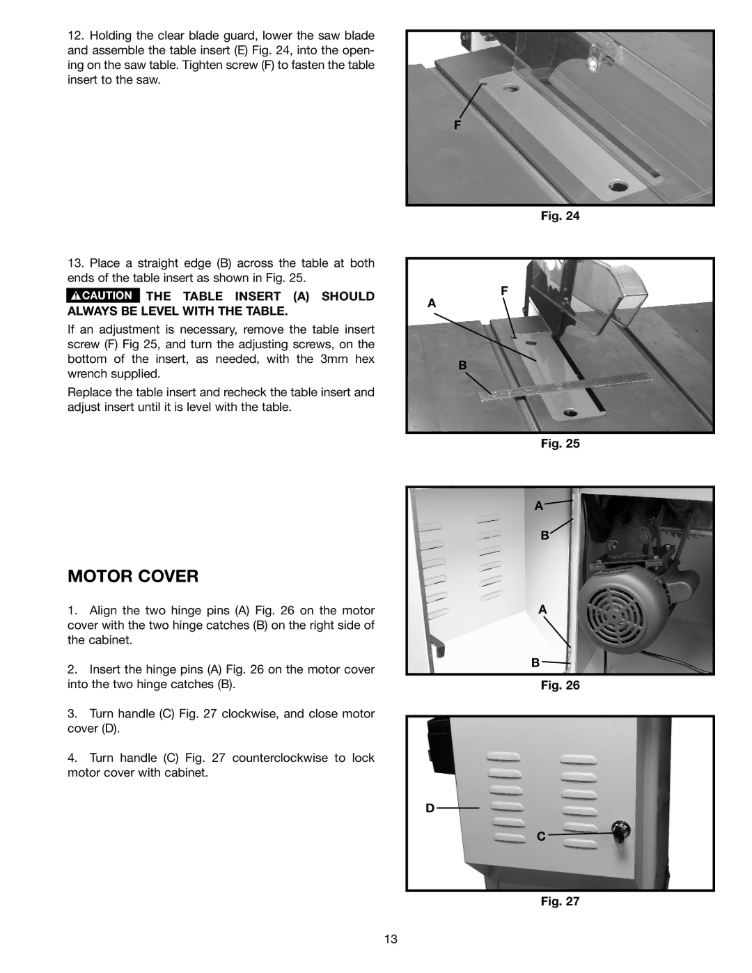
12.Holding the clear blade guard, lower the saw blade and assemble the table insert (E) Fig. 24, into the open- ing on the saw table. Tighten screw (F) to fasten the table insert to the saw.
13.Place a straight edge (B) across the table at both ends of the table insert as shown in Fig. 25.
 THE TABLE INSERT (A) SHOULD ALWAYS BE LEVEL WITH THE TABLE.
If an adjustment is necessary, remove the table insert screw (F) Fig 25, and turn the adjusting screws, on the bottom of the insert, as needed, with the 3mm hex wrench supplied.
Replace the table insert and recheck the table insert and adjust insert until it is level with the table.
MOTOR COVER
1.Align the two hinge pins (A) Fig. 26 on the motor cover with the two hinge catches (B) on the right side of the cabinet.
2.Insert the hinge pins (A) Fig. 26 on the motor cover into the two hinge catches (B).
3.Turn handle (C) Fig. 27 clockwise, and close motor cover (D).
4.Turn handle (C) Fig. 27 counterclockwise to lock motor cover with cabinet.
F
Fig. 24
F
A
B
Fig. 25
A ![]()
B
A
B ![]()
Fig. 26
D
C ![]()
Fig. 27
13
