ADJUSTING TABLE
The saw table has been aligned at the factory so the miter gage slots are parallel to the saw blade; however, it is recommended to check the alignment before initial operation as follows:
DISCONNECT MACHINE FROM POWER
SOURCE.
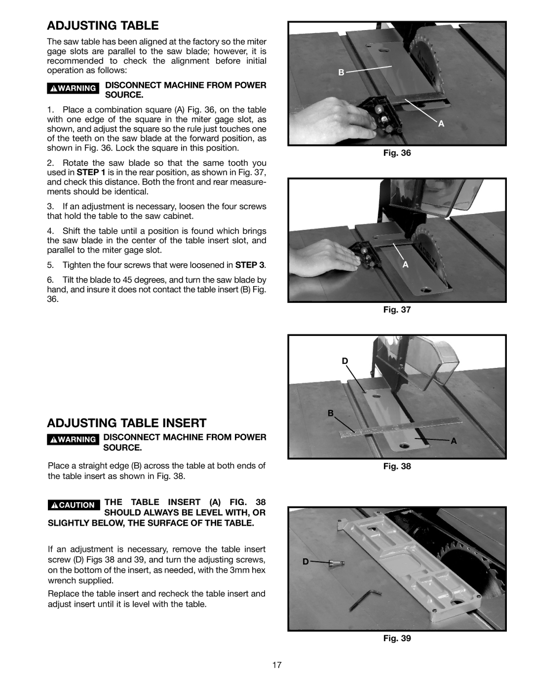
1.Place a combination square (A) Fig. 36, on the table with one edge of the square in the miter gage slot, as shown, and adjust the square so the rule just touches one of the teeth on the saw blade at the forward position, as shown in Fig. 36. Lock the square in this position.
2.Rotate the saw blade so that the same tooth you used in STEP 1 is in the rear position, as shown in Fig. 37, and check this distance. Both the front and rear measure- ments should be identical.
3.If an adjustment is necessary, loosen the four screws that hold the table to the saw cabinet.
4.Shift the table until a position is found which brings the saw blade in the center of the table insert slot, and parallel to the miter gage slot.
5.Tighten the four screws that were loosened in STEP 3.
6.Tilt the blade to 45 degrees, and turn the saw blade by hand, and insure it does not contact the table insert (B) Fig.
ADJUSTING TABLE INSERT
DISCONNECT MACHINE FROM POWER
SOURCE.
Place a straight edge (B) across the table at both ends of the table insert as shown in Fig. 38.
THE TABLE INSERT (A) FIG. 38
SHOULD ALWAYS BE LEVEL WITH, OR SLIGHTLY BELOW, THE SURFACE OF THE TABLE.
If an adjustment is necessary, remove the table insert screw (D) Figs 38 and 39, and turn the adjusting screws, on the bottom of the insert, as needed, with the 3mm hex wrench supplied.
Replace the table insert and recheck the table insert and adjust insert until it is level with the table.
B ![]()
A
Fig. 36
A
Fig. 37
D
B
![]() A
A
Fig. 38
D ![]()
Fig. 39
17