MITER GAGE OPERATION AND ADJUSTMENT
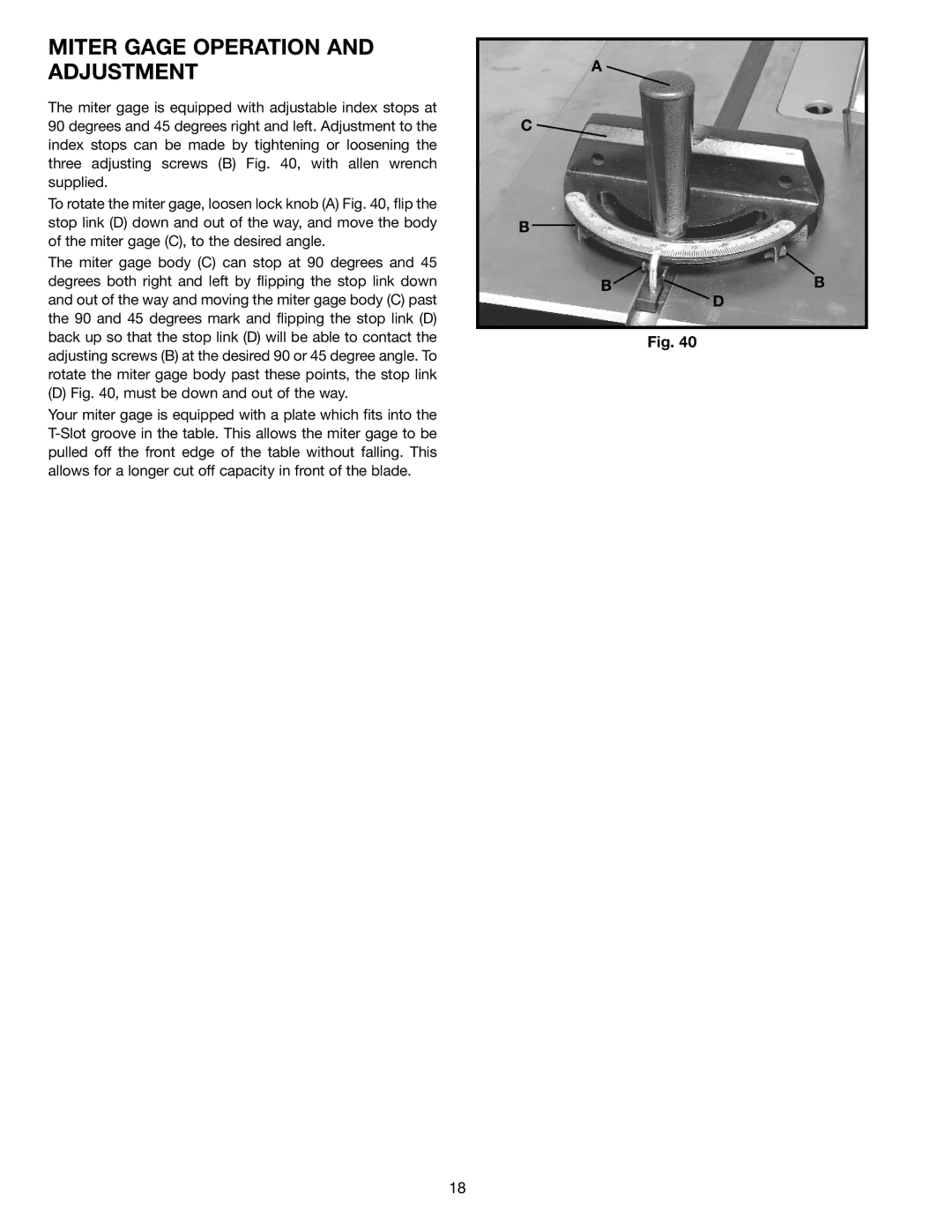
The miter gage is equipped with adjustable index stops at 90 degrees and 45 degrees right and left. Adjustment to the index stops can be made by tightening or loosening the three adjusting screws (B) Fig. 40, with allen wrench supplied.
To rotate the miter gage, loosen lock knob (A) Fig. 40, flip the stop link (D) down and out of the way, and move the body of the miter gage (C), to the desired angle.
The miter gage body (C) can stop at 90 degrees and 45 degrees both right and left by flipping the stop link down and out of the way and moving the miter gage body (C) past the 90 and 45 degrees mark and flipping the stop link (D) back up so that the stop link (D) will be able to contact the adjusting screws (B) at the desired 90 or 45 degree angle. To rotate the miter gage body past these points, the stop link
(D) Fig. 40, must be down and out of the way.
Your miter gage is equipped with a plate which fits into the T-Slot groove in the table. This allows the miter gage to be pulled off the front edge of the table without falling. This allows for a longer cut off capacity in front of the blade.
A ![]()
C
B
B![]() B
B
D
Fig. 40
18