Repeat step 5, if necessary, until the light and marking are aligned.
6.Adjust the other laser in the same manner. Two parallel laser markings should look like O and P in Figure 22 – the distance between the lines will vary with board thickness; however, the lines must be parallel.
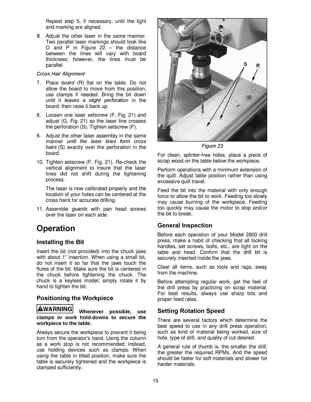
Cross Hair Alignment
7.Place board (R) flat on the table. Do not allow the board to move from this position; use clamps if needed. Bring the bit down until it leaves a slight perforation in the board; then raise it back up.
8.Loosen one laser setscrew (F, Fig. 21) and adjust (G, Fig. 21) so the laser line crosses the perforation (S). Tighten setscrew (F).
9.Adjust the other laser assembly in the same manner until the laser lines form cross hairs (S) exactly over the perforation in the board.
10.Tighten setscrew (F, Fig. 21).
The laser is now calibrated properly and the location of your holes can be centered at the cross hairs for accurate drilling.
11.Assemble guards with pan head screws over the laser on each side.
Operation
Installing the Bit
Insert the bit (not provided) into the chuck jaws with about 1” insertion. When using a small bit, do not insert it so far that the jaws touch the flutes of the bit. Make sure the bit is centered in the chuck before tightening the chuck. The chuck is a keyless model; simply rotate it by hand to tighten the bit.
Positioning the Workpiece
![]() Whenever possible, use clamps or work
Whenever possible, use clamps or work
Always secure the workpiece to prevent it being torn from the operator’s hand. Using the column as a work stop is not recommended; instead, use holding devices such as clamps. When using the table in tilted position, make sure the table is securely tightened and the workpiece is clamped sufficiently.
Figure 23
For clean,
Perform operations with a minimum extension of the quill. Adjust table position rather than using excessive quill travel.
Feed the bit into the material with only enough force to allow the bit to work. Feeding too slowly may cause burning of the workpiece. Feeding too quickly may cause the motor to stop and/or the bit to break.
General Inspection
Before each operation of your Model 2800 drill press, make a habit of checking that all locking handles, set screws, bolts, etc., are tight on the table and head. Confirm that the drill bit is securely inserted inside the jaws.
Clear all items, such as tools and rags, away from the machine.
Before attempting regular work, get the feel of the drill press by practicing on scrap material. For best results, always use sharp bits and proper feed rates.
Setting Rotation Speed
There are several factors which determine the best speed to use in any drill press operation, such as kind of material being worked, size of hole, type of drill, and quality of cut desired.
A general rule of thumb is, the smaller the drill, the greater the required RPMs. And the speed should be faster for soft materials and slower for harder materials.
15