Router modules | 1 |
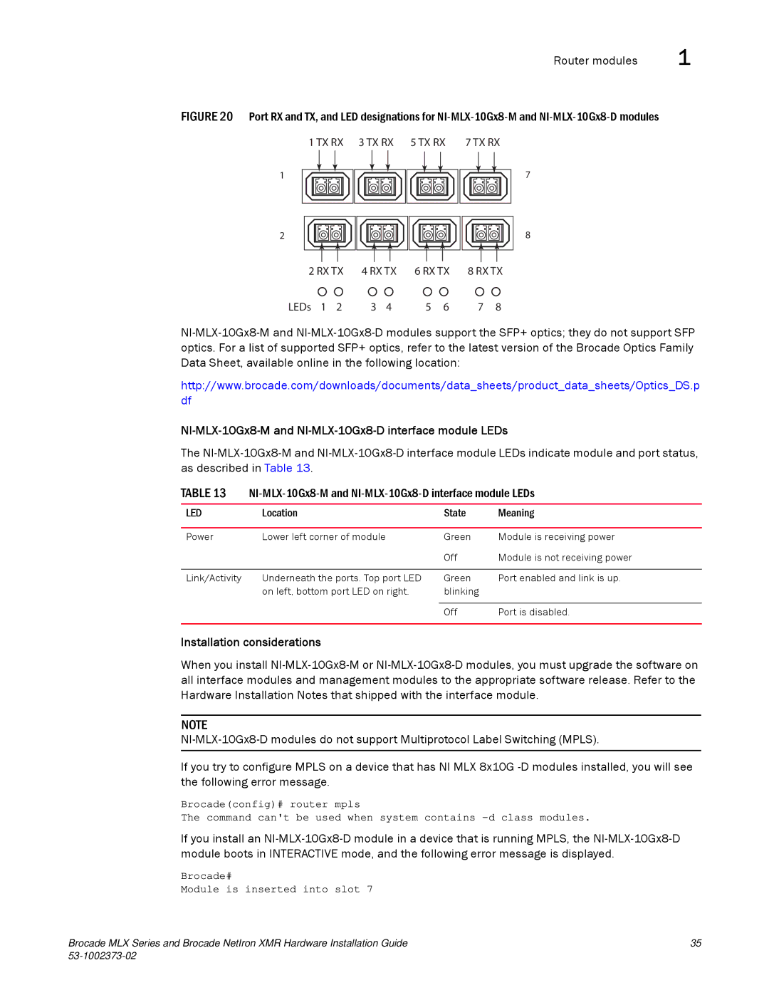
FIGURE 20 Port RX and TX, and LED designations for NI-MLX-10Gx8-M and NI-MLX-10Gx8-D modules
1 TX RX 3 TX RX 5 TX RX | 7 TX RX |
1
7
2
8 |
2 RX TX | 4 RX TX | 6 RX TX | 8 RX TX | |||||
LEDs | 1 | 2 | 3 | 4 | 5 | 6 | 7 | 8 |
http://www.brocade.com/downloads/documents/data_sheets/product_data_sheets/Optics_DS.p df
NI-MLX-10Gx8-M and NI-MLX-10Gx8-D interface module LEDs
The
TABLE 13
LED | Location | State | Meaning |
|
|
|
|
Power | Lower left corner of module | Green | Module is receiving power |
|
| Off | Module is not receiving power |
|
|
|
|
Link/Activity | Underneath the ports. Top port LED | Green | Port enabled and link is up. |
| on left, bottom port LED on right. | blinking |
|
|
|
|
|
|
| Off | Port is disabled. |
|
|
|
|
Installation considerations
When you install
NOTE
If you try to configure MPLS on a device that has NI MLX 8x10G
Brocade(config)# router mpls
The command can't be used when system contains
If you install an
Brocade#
Module is inserted into slot 7
Brocade MLX Series and Brocade NetIron XMR Hardware Installation Guide | 35 |
|