Verifying proper operation | 2 |
TABLE 33 Router LED states and actions (Continued)
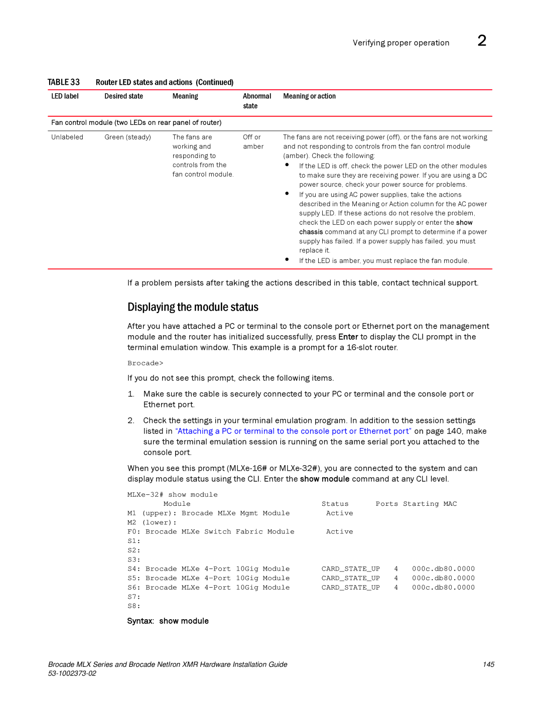
LED label | Desired state | Meaning | Abnormal | Meaning or action |
|
|
| state |
|
Fan control module (two LEDs on rear panel of router)
Unlabeled | Green (steady) | The fans are | Off or | The fans are not receiving power (off), or the fans are not working |
|
| working and | amber | and not responding to controls from the fan control module |
|
| responding to |
| (amber). Check the following: |
|
| controls from the |
| • If the LED is off, check the power LED on the other modules |
|
| fan control module. |
| to make sure they are receiving power. If you are using a DC |
|
|
|
| power source, check your power source for problems. |
|
|
|
| • If you are using AC power supplies, take the actions |
|
|
|
| described in the Meaning or Action column for the AC power |
|
|
|
| supply LED. If these actions do not resolve the problem, |
|
|
|
| check the LED on each power supply or enter the show |
|
|
|
| chassis command at any CLI prompt to determine if a power |
|
|
|
| supply has failed. If a power supply has failed, you must |
|
|
|
| replace it. |
|
|
|
| • If the LED is amber, you must replace the fan module. |
|
|
|
|
|
If a problem persists after taking the actions described in this table, contact technical support.
Displaying the module status
After you have attached a PC or terminal to the console port or Ethernet port on the management module and the router has initialized successfully, press Enter to display the CLI prompt in the terminal emulation window. This example is a prompt for a
Brocade>
If you do not see this prompt, check the following items.
1.Make sure the cable is securely connected to your PC or terminal and the console port or Ethernet port.
2.Check the settings in your terminal emulation program. In addition to the session settings listed in “Attaching a PC or terminal to the console port or Ethernet port” on page 140, make sure the terminal emulation session is running on the same serial port you attached to the console port.
When you see this prompt
Status | Ports Starting MAC | ||
M1 | Module | ||
(upper): Brocade MLXe Mgmt Module | Active |
| |
M2 | (lower): | Active |
|
F0: Brocade MLXe Switch Fabric Module |
| ||
S1: |
|
| |
S2: |
|
| |
S3: |
|
| |
S4: Brocade MLXe | CARD_STATE_UP | 4 | 000c.db80.0000 |
S5: Brocade MLXe | CARD_STATE_UP | 4 | 000c.db80.0000 |
S6: Brocade MLXe | CARD_STATE_UP | 4 | 000c.db80.0000 |
S7: |
|
|
|
S8: |
|
|
|
Syntax: show module
Brocade MLX Series and Brocade NetIron XMR Hardware Installation Guide | 145 |
|
|