Router modules | 1 |
POS module LEDs
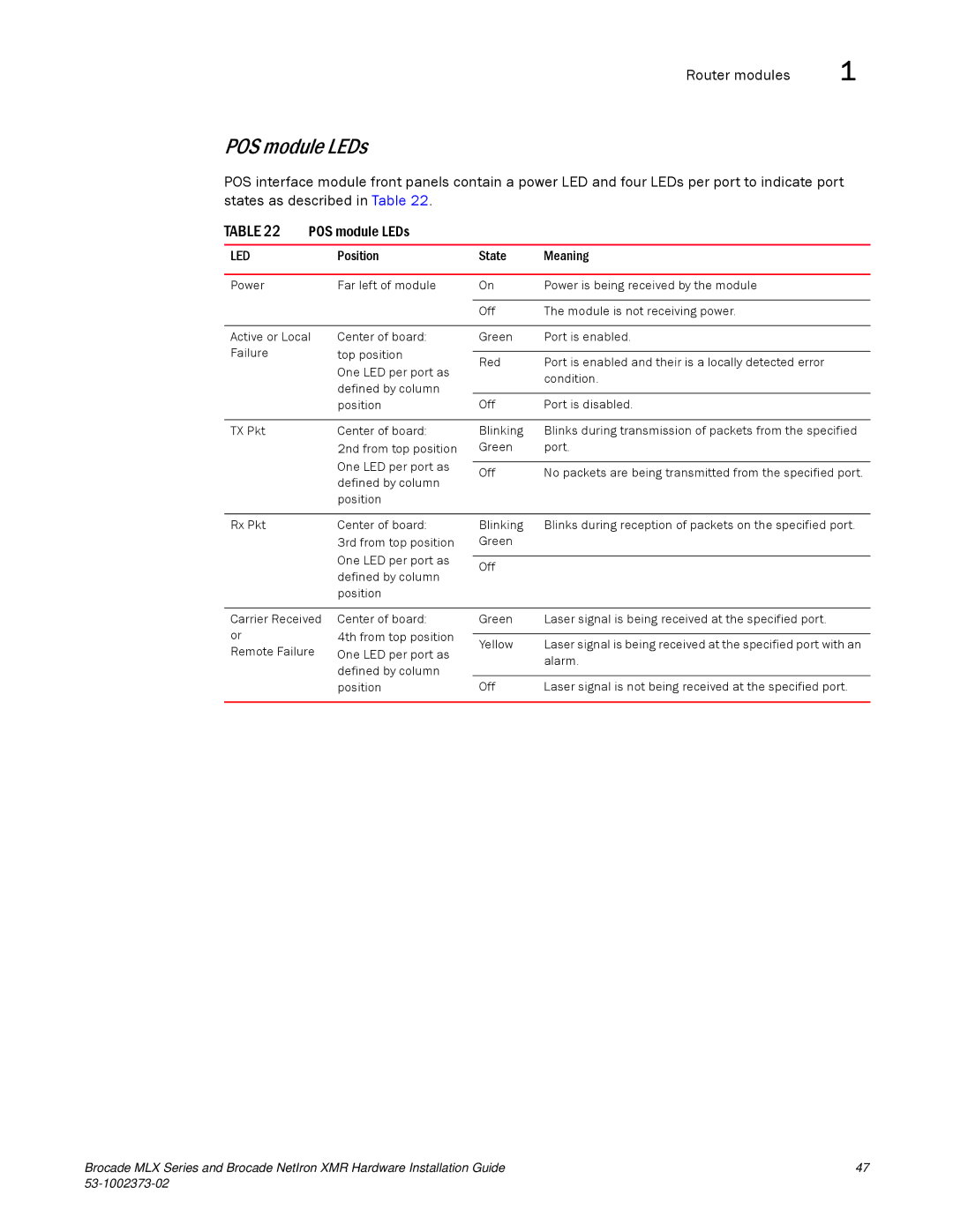
POS interface module front panels contain a power LED and four LEDs per port to indicate port states as described in Table 22.
TABLE 22 | POS module LEDs |
|
| |
|
|
|
|
|
LED |
| Position | State | Meaning |
|
|
|
|
|
Power |
| Far left of module | On | Power is being received by the module |
|
|
|
|
|
|
|
| Off | The module is not receiving power. |
|
|
|
| |
Active or Local | Center of board: | Green | Port is enabled. | |
Failure |
| top position |
|
|
| Red | Port is enabled and their is a locally detected error | ||
|
| One LED per port as | ||
|
|
| condition. | |
|
| defined by column |
| |
|
|
|
| |
|
| position | Off | Port is disabled. |
|
|
|
|
|
TX Pkt |
| Center of board: | Blinking | Blinks during transmission of packets from the specified |
|
| 2nd from top position | Green | port. |
|
| One LED per port as |
|
|
|
| Off | No packets are being transmitted from the specified port. | |
|
| defined by column | ||
|
|
|
| |
position
Rx Pkt | Center of board: |
| 3rd from top position |
| One LED per port as |
| defined by column |
| position |
Blinking | Blinks during reception of packets on the specified port. |
Green |
|
|
|
Off |
|
Carrier Received or
Remote Failure
Center of board:
4th from top position One LED per port as defined by column position
Green | Laser signal is being received at the specified port. |
|
|
Yellow | Laser signal is being received at the specified port with an |
| alarm. |
|
|
Off | Laser signal is not being received at the specified port. |
Brocade MLX Series and Brocade NetIron XMR Hardware Installation Guide | 47 |
|